Samsung Electronics
1-4
1-4-1 Warnings
1. When servicing, do not approach the LASER
exit with the eye too closely. In case it is
necessary to confirm LASER beam emission,
be sure to observe from a distance of more
than 30 cm from the surface of the objective
lens on the optical pick-up block.
2. Do not attempt to handle the objective lens
when the DISC is not on the tray.
3. When servicing, do not approach the LASER
exit with the eye too closely. In case it is
necessary to confirm LASER beam emission,
be sure to observe from a distance of more
than 30 cm from the surface of the objective
lens on the optical pick-up block.
4. Do not attempt to handle the objective lens
when the DISC is not on the tray.
1-4-2 Laser Diode Specifications
Material: GaAs+ GaAlAs
Wavelength: 760-800 nm
Emission Duration: Continuous
Laser Output: 0.2 mw (measured at a
1.6 mm distance from the objective lens
surface on the optical pick-up block.)
1-4-3 Handling the Optical Pick-up
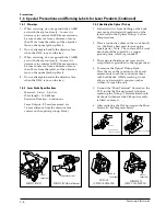
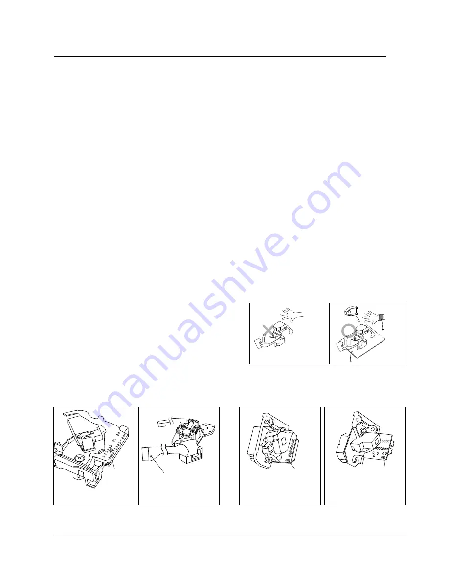
1. Static electricity from clothing or the body
may cause electrostatic breakdown of the
laser diode in the Optical Pickup. Follow
this procedure:
2. Place a conductive sheet on the work bench
(i.e., the black sheet used for wrapping
repair parts.) Note: The surface of the work
bench should be covered by a copper
ground plane, which is grounded.
3. The repair technician must wear a wrist
strap which is grounded to the copper sheet.
4. To remove the Optical Pickup block:
Place the set on the conductive sheet, and
momentarily touch the conductive sheet
with both hands. (While working, do not
allow any electrostatic sources--such as
clothes--to touch the unit.
5. Ground the "Short Terminal" (located on the
PCB, inside the Pickup Assembly) before
replacing the Pickup. This terminal should
be shorted whenever the Pickup Assembly
is lifted or moved.
6. After replacing the Pickup, reopen the Short
Terminal. See diagrams below:
1-4 Special Precautions and Warning Labels for Laser Products (Continued)
THE UNIT
(1) WRIST-STRAP
FOR GROUNDING
1M
1M
CONDUCTIVE SHEET
short
terminal
short terminal
short
terminal
short
terminal
SOH91VI(LDP)
SOH91CI(CAR,walkman)
SOH94T4N
(CMS-V10,CMS-V30)
SOH-A1
(CMS-V10,CMS-V30)
Precautions
Summary of Contents for DV7720KV
Page 21: ...Samsung Electronics 5 2 5 1 Adjustment Point Location Alignment and Adjustment ...
Page 150: ...Samsung Electronics 8 1 8 Block Diagram ...
Page 151: ...Samsung Electronics 9 1 9 PCB Diagram 9 1 Front Top DV7720KV ...
Page 152: ...Samsung Electronics 9 2 PCB Diagram 9 2 Front Top DV4720KV ...
Page 153: ...Samsung Electronics 9 3 PCB Diagram 9 3 Video cd 9 4 1 Top view 9 4 2 Bottom view ...
Page 154: ...Samsung Electronics 9 4 PCB Diagram 9 3 Main ...
Page 155: ...Samsung Electronics 9 5 PCB Diagram ...
Page 156: ...Samsung Electronics 9 6 PCB Diagram 9 5 Power ...
Page 157: ...Samsung Electronics 9 7 PCB Diagram 9 6 Deck ...
Page 158: ...Samsung Electronics 9 8 PCB Diagram 9 7 Deck 9 8 Deck ...
Page 159: ...Samsung Electronics 10 1 10 Wiring Diagram Fig 10 1 Wiring Diagram DV7720KV DV4720V ...
Page 160: ...Samsung Electronics 10 2 Wiring Diagrams Fig 10 2 Wiring Diagram DV7700KV DV4700V ...
Page 161: ...Samsung Electronics 11 1 Schematic Diagrams 11 Schematic Diagram 11 1 Front ...
Page 162: ...Samsung Electronics 11 2 Schematic Diagrams 11 2 Main 1 4 Servo Section ...
Page 163: ...Samsung Electronics 11 3 Schematic Diagrams 11 3 Main 2 4 LD Video Section ...
Page 164: ...Samsung Electronics 11 4 Schematic Diagrams 11 4 Main 3 4 Audio Section ...
Page 165: ...Samsung Electronics 11 5 Schematic Diagrams 11 5 Main 4 4 Syscon Section ...
Page 166: ...Schematic Diagrams 11 Ð 6 Samsung Electronics 11 6 Video CD ...
Page 167: ...Samsung Electronics 11 7 Schematic Diagrams 11 8 Power DV 7620KV DV 7622KV ...


