5-10
Samsung Electronics
Disassembly/Reaasembly
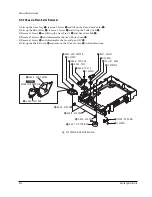
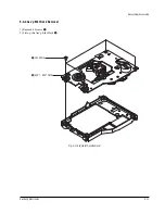
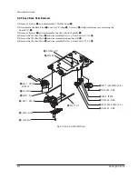
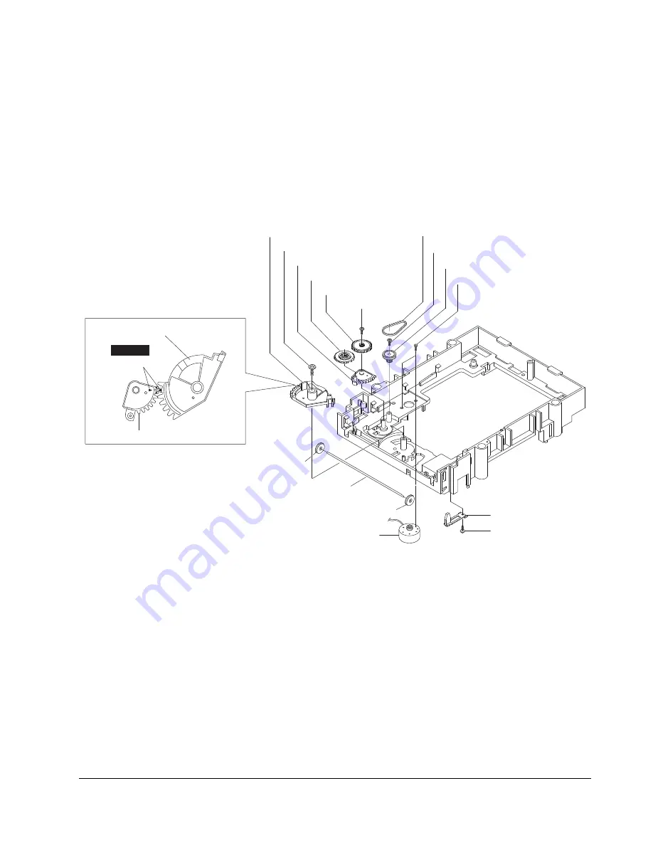
5-4-3 Chassis-Main Parts Removal
1) Lift up the Gear-Tray
Œ
, remove 1 Screw
´
and lift up the Gear-Cam Center
ˇ
.
2) Lift up the Belt-Pulley
¨
, remove 1 Screw
ˆ
and lift up the Pulley-Gear
Ø
.
3) Remove 1 Screw
∏
and lift up the Gear-Tray A
”
and Gear-Cam Sub
’
.
4) Remove 2 Screws
˝
and disassemble the AssÕy-Motor Load
Ô
.
5) Remove 1 Screw
and disassemble the Lever-Open S/W
Ò
.
6) Lift up the Shaft-Syncro
Ú
and remove the 2 Gear-Syncro
Æ
in both directions.
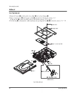
Fig. 5-10 Chassis-Main Parts Removal
¨
BELT - PULLEY
ˆ
1 SCREW
”
GEAR - TRAY A
∏
1 SCREW
Ø
PULLEY - GEAR
˝
2 SCREWS
´
1 SCREW
ˇ
GEAR - CAM CENTER
ˇ
GEAR - CAM CENTER
Ô
ASS'Y - MOTOR LOAD
Ú
SHAFT - SYNCRO
Æ
GEAR - SYNCRO
Æ
GEAR - SYNCRO
Ò
LEVER - OPEN S/W
Œ
GEAR - TRAY
’
GEAR - CAM SUB
’
GEAR - CAM SUB
1 SCREW
TIMING
ALIGN TWO ARROWS
Summary of Contents for DVD-739
Page 23: ...Reference Information 2 16 Samsung Electronics MEMO ...
Page 25: ...Product Specification 3 2 Samsung Electronics MEMO ...
Page 29: ...Operating Instructions 4 4 Samsung Electronics MEMO ...
Page 77: ...Exploded Views and Parts List 8 6 Samsung Electronics MEMO ...
Page 87: ...Block Diagrams 10 2 Samsung Electronics MEMO ...
Page 89: ...PCB Diagrams 11 2 Samsung Electronics 11 1 Main COMPONENT SIDE SOLDER SIDE ...
Page 90: ...PCB Diagrams Samsung Electronics 11 3 11 2 Jack ...
Page 91: ...PCB Diagrams 11 4 Samsung Electronics 11 5 Deck 11 4 Play 11 3 Power ...
Page 92: ...Samsung Electronics 12 1 12 Wiring Diagram JACK PCB MAIN PCB DECK PCB PLAY PCB POWER PCB ...
Page 93: ...Wiring Diagram 12 2 Samsung Electronics MEMO ...
Page 95: ...Schematic Diagrams 13 2 Samsung Electronics 13 1 S M P S ...
Page 96: ...Schematic Diagrams Samsung Electronics 13 3 13 2 Main Power Supply ...
Page 97: ...Schematic Diagrams 13 4 Samsung Electronics 13 3 Main Micom ...
Page 98: ...Schematic Diagrams Samsung Electronics 13 5 13 4 Servo ...
Page 99: ...Schematic Diagrams 13 6 Samsung Electronics 13 5 Video Y Output C Output CVBS Output ...
Page 100: ...Schematic Diagrams Samsung Electronics 13 7 13 6 Audio ...
Page 101: ...Schematic Diagrams 13 8 Samsung Electronics KCN1 KCN2 13 7 5 1 Channel Audio DVD 929K Only ...
Page 102: ...Schematic Diagrams Samsung Electronics 13 9 13 8 RF ...
Page 103: ...Schematic Diagrams 13 10 Samsung Electronics 13 9 ZiVA ...
Page 104: ...Schematic Diagrams Samsung Electronics 13 11 13 10 DSP ...
Page 107: ...Schematic Diagrams 13 14 Samsung Electronics 13 13 Mute ...
Page 108: ...Schematic Diagrams Samsung Electronics 13 15 13 14 Karaoke Power ...
Page 109: ...Schematic Diagrams 13 16 Samsung Electronics 13 15 Play ...
Page 110: ...Schematic Diagrams Samsung Electronics 13 17 13 16 Deck ...
Page 111: ...Schematic Diagrams 13 18 Samsung Electronics 13 17 Remote Control ...


