3-4
Software Update
Samsung Electronics
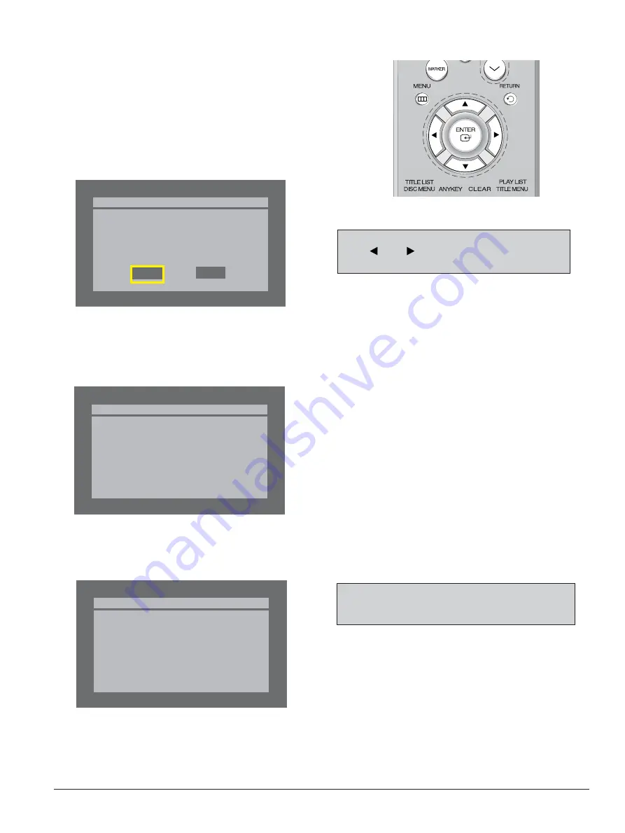
Fig. 3-6
* If you don’t see the message above, try another disc.
Generally, this is caused by disc quality and by disc creating problem.
4) Press the
ENTER
button on the remote control (Fig. 3-7).
Fig. 3-8
5) It takes about 5 minutes to complete the update.
The message below will be displayed in the screen after update is completed and the tray will open automatically.
Fig. 3-9
6) After removing the update disc, turn off the unit with power button.
And there after turn on the unit with power button and then the will be closed.
The Flash update is now completed.
* If the message to the left isn’t displayed after 10minutes
and the unit is no longer functioning properly, contact a
samsung authorized service center.
Atfer checking old and new version, select “Yes” or “No”
with
“
”
or
“ ”
on the remote control.
* The Version is indicated by “YYMMDD.xx modelname”
Flash Update
Do you want to update flash memory?
Version : YYMMDD.xx.R129
-> YYMMDD.xx.R129
No
Yes
Flash Update
Now, Processing...
Plase. do not turn off the power.
Flash Update
Flash memory is successfully
updated.
1) Press
OPEN/CLOSE
to open the disc tray.
2) Insert the update CD-R disc with the software update, label
facing up.
3) Press
OPEN/CLOSE
to close the disc tray.
Fig. 3-7 Remote Control
Summary of Contents for DVD-R129XAA
Page 4: ...14 Reference Information 14 1 14 4 14 1 About IEEE 1394 14 1 CONTENTS ...
Page 10: ...Precautions 1 6 Samsung Electronics MEMO ...
Page 22: ...Product Specification 2 12 Samsung Electronics MEMO ...
Page 49: ...Samsung Electronics 6 1 6 Exploded View and Parts List 6 1 Cabinet Assembly Page 6 2 ...
Page 52: ...Exploded Views and Parts List 6 4 Samsung Electronics MEMO ...
Page 73: ...Samsung Electronics 9 1 9 Wiring Diagram ...
Page 74: ...Wiring Diagram 9 2 Samsung Electronics MEMO ...
Page 77: ...PCB Diagrams Samsung Electronics 10 3 FIC1 DIC5 DIC4 VIC1 CONDUCTOR SIDE ...
Page 80: ...PCB Diagrams 10 6 Samsung Electronics 10 3 Key PCB COMPONENT SIDE CONDUCTOR SIDE ...
Page 81: ...PCB Diagrams Samsung Electronics 10 7 10 4 Sub PCB COMPONENT SIDE CONDUCTOR SIDE ...
Page 82: ...PCB Diagrams 10 8 Samsung Electronics MEMO ...
Page 114: ...Operating Instructions 12 18 Samsung Electronics MEMO ...
Page 130: ...Circuit Operating Descriptions 13 16 Samsung Electronics MEMO ...
Page 134: ...Reference Information 14 4 Samsung Electronics MEMO ...
Page 139: ... Product Specification ...
Page 140: ... Chassis Product Specification ...
Page 141: ......
Page 142: ......
Page 143: ...4 Disassembly and Reassembly ...
Page 144: ......
Page 145: ......
Page 146: ......
Page 147: ......
Page 148: ......
Page 149: ...5 Specifications ...
Page 156: ......
Page 161: ......
Page 162: ... Block diagram ...
Page 166: ...7 11 Tuner Demodulator Block diagram of Tuner ...
Page 189: ...8 Troubleshooting ...
Page 190: ......
Page 191: ......
Page 192: ......
Page 193: ......
Page 194: ......
Page 195: ......
Page 196: ......
Page 197: ......
Page 198: ......
Page 199: ......
Page 200: ......
Page 201: ......
Page 202: ......
Page 203: ......
Page 204: ......
Page 205: ...9 Software Upgrade ...
Page 206: ......
Page 207: ......
Page 208: ......


