88
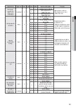
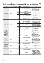
Basic segment display
Step
Display content
Display
At initial power input
Checking segment display
SEG 1
SEG 2
SEG 3
SEG 4
“8”
“8”
“8”
“8”
While setting communication
between indoor and outdoor unit
(Addressing)
Number of connected indoor units
SEG 1
SEG 2
SEG 3
SEG 4
“A”
“d”
Number of communicated
units
❋
Refer to "View Mode"
for communication
address
After communication setting
(usual occasion)
Transmit/Reception address
SEG 1
SEG 2
SEG 3
SEG 4
I/U: “A”
MCU: “C”
I/U: “0”
MCU: “1”
Reception address (in
decimal number)
❇
I/U : Indoor unit
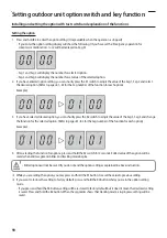
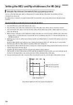
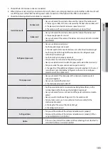
Setting outdoor unit option switch and key function
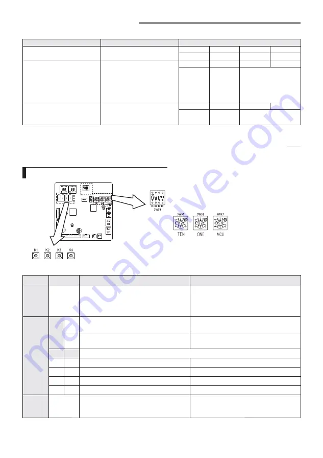
Setting outdoor unit option switches : A TYPE
❇
If you install HR products, you must match the address between the MCU and the indoor unit.
Switch
Setting
Function
Remarks
SW51 /
SW52
Setting total number of installed indoor unit
SW51: Tens digit, SW52: Units digit
Setting can be done from the main outdoor unit
only (sub unit: setting is unnecessary)
Ex) When 12 indoor units are installed
SW51: 1,
SW52: 2
SW53
K6
On
Enable maximum capacity restriction for cooling
operation
Restrict excessive capacity increase when
operating indoor units with small capacity
Off
Disable maximum capacity restriction for cooling
operation
-
K7
K8
Selecting outdoor unit address
On
On
Outdoor unit address: No. 1
Main unit
On
Off
Outdoor unit address: No. 2
Sub unit 1
Off
On
Outdoor unit address: No. 3
Sub unit 2
Off
Off
Outdoor unit address: No. 4
Sub unit 3
SW57
Setting total number of connected MCU
Setting can be done from Main unit only.
Ex) When 3 MCUs are installed
´
SW57:3, When
10 MCUs are installed
´
SW57:A
Summary of Contents for DVM S AM080FXVAGH
Page 112: ......

