PCB Diagram _ 43
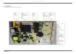
5. PCB DIAGRAM
5-1. MAIN PBA
► This Document can not be used without Samsung’s authorization.
4
1
2
5
6
7
3
8
9
10
11
12
13
14
NO
Location
Description
1
CON1
Connector for AC input
2
CON2
Connector for drain motor, washing motor
3
P01
Connector for heater
4
P02
Connector for heater
5
CN6
Connector for door switch, dispenser
6
CN5
Connector for door switch, water valve
7
CN2
Connector for sub PCBA
8
CN3
Sensing connector(refer to next page for details )
9
CN4
Sensing connector(refer to next page for details )
10
CN10
Connector for program
11
CN9
Connector for DC fan
12
RY1
Relay for drain motor
13
RY2
Relay for washing motor
14
RY6
Relay for heater
All manuals and user guides at all-guides.com


