Samsung DX7-A, Mechanical Manual
The Samsung DX7-A Mechanical Manual is essential for mastering your Samsung DX7-A product. This comprehensive manual provides step-by-step instructions, troubleshooting tips, and essential maintenance guidelines. Download the free manual now from 88.208.23.73:8080 to optimize your experience and unleash the full potential of your Samsung DX7-A.
Share
Download


Reviews:
No comments
Related manuals for DX7-A

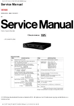
PV-V464S
Brand: Panasonic Pages: 4

PV-V4624S
Brand: Panasonic Pages: 4

AJ-D960
Brand: Panasonic Pages: 124
AJ-D455
Brand: Panasonic Pages: 24
PV-V4524S
Brand: Panasonic Pages: 4
NV-P05REE
Brand: Panasonic Pages: 11
OmniVision PV-QV200
Brand: Panasonic Pages: 34
NV-P05REE
Brand: Panasonic Pages: 52
AJ-YA120AG
Brand: Panasonic Pages: 56
Omnivision PV-9661
Brand: Panasonic Pages: 407

NV-HD630 series
Brand: Panasonic Pages: 112

Omnivision PV-V4523S
Brand: Panasonic Pages: 4

Omnivision VHS PV-V4022
Brand: Panasonic Pages: 4

AG710P - VCR/BRC
Brand: Panasonic Pages: 20

NV-SJ230A
Brand: Panasonic Pages: 22

AJ-HD3700H
Brand: Panasonic Pages: 22

Omnivision PV-HD1000
Brand: Panasonic Pages: 48

NV-L20A
Brand: Panasonic Pages: 35


