background image

English  7

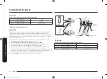
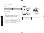
Connecting the power

Connecting the power

Step 1. Meeting electrical connection requirements

CAUTION

For personal safety, do not use an extension cord with this appliance. Remove the 
house fuse or open the circuit breaker before beginning installation.

This appliance must be supplied with the proper voltage and frequency, and be 
connected to an individual, properly grounded branch circuit, protected by a 
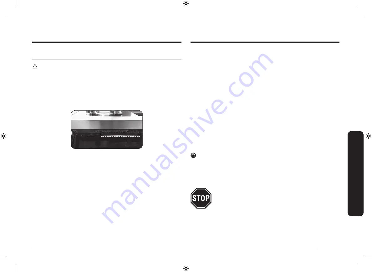
circuit breaker or fuse having amperage as specified on the rating plate. The rating 
plate is located on the bottom side of the control panel.

We recommend you have the electrical wiring and hookup of your range 
connected by a qualified electrician. After installation, have the electrician show 
you where your main range disconnect is located.

Check with your local utilities for electrical codes which apply in your area. Failure 
to wire your oven according to governing codes could result in a hazardous 
condition. If there are no local codes, your range must be wired and fused to meet 
the requirements of the National Electrical Code, ANSI/NFPA No. 70–Latest Edition. 
You can get a copy by writing:

National Fire Protection Association 
Batterymarch Park 
Quincy, MA 02269

Effective January 1, 1996, the National Electrical Code requires that new 
construction (not existing) utilize a 4-conductor connection to an electric range.

When installing an electric range in new construction, follow Steps 2 and 3 for a 
4-wire connection.

You must use a 3-wire or 4-wire, single-phase A.C. 208Y/120 Volt or 
240/120 Volt, 60 hertz electrical system.

If the electrical service provided does not meet the above specifications, have a 
licensed electrician install an approved outlet.

Use only a 3-conductor or a 4-conductor UL-listed range cord. These cords may be 
provided with ring terminals on the wire and a strain relief device.

A range cord rated at 40 amps with 125/250 minimum volt range is required. 
A 50 amp range cord is not recommended but if used, it should be marked for 
use with nominal 1

3

8

" diameter connection openings. Care should be taken to 

center the cable and strain relief within the knockout hole to keep the edge from 
damaging the cable.
•  Because range terminals are not accessible after the range is in position, a 

flexible service conduit or cord must be used.

NOTE

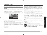
If the power connection is plugged in improperly, the following message appears 
on the display.
•  LCD, PMOLED : Wire installation fail
•  LED : bAd LinE
Reconnect the power connection properly, and the message disappears.

ALL NEW BRANCH-CIRCUIT CONSTRUCTIONS, MOBILE HOMES, 
RECREATIONAL VEHICLES, AND INSTALLATIONS WHERE LOCAL 
CODES DO NOT ALLOW GROUNDING THROUGH NEUTRAL, REQUIRE 
A 4-CONDUCTOR UL-LISTED RANGE CORD.

Install_NE63T8911_AA_DG68-01257A-00_EN.indd   7

2020-03-26     6:27:50

Summary of Contents for Electric Range NE63 8 Series

Page 1: ...Electric Range Installation manual NE63 8 Install_NE63T8911_AA_DG68 01257A 00_EN indd 1 2020 03 26 6 27 49 ...

Page 2: ...A A child or adult can tip the range and be killed B Install the anti tip device to the structure and or the range at rear right or rear left of the range bottom C Engage the range to the anti tip device by leveling leg at rear right or rear left of the range bottom D Re engage the anti tip device if the range is moved E See installation instructions for details F Failure to do so can result in de...

Page 3: ...range should not be placed on a base For your safety WARNING If the information in this manual is not followed exactly a fire or electrical shock may result causing property damage personal injury or death Before beginning the installation switch the power off at the service panel and lock the service disconnecting switch to prevent power from being switched on accidentally When the service discon...

Page 4: ...mum allowable wood cabinet temperatures of 194 F Make sure the wall covering countertops and cabinets around the range can withstand the heat up to 194 F generated by the range If not discoloration delamination or melting may occur A B 36 363 4 293 4 267 16 491 4 2811 16 2915 16 357 8 25 24 6 3 24 3 A Cabinet opening min 30 76 2 cm B Acceptable electrical outlet area IMPORTANT If your cabinets are...

Page 5: ...mum 3 from cutout to side edges of the countertop Optional rear filler kit Used to fill gap between the range back and wall Adds a filler strip to the rear of the range This kit can only be used when the opening in the countertop is 25 deep 1 Unscrew the screws affixing the vent cover 2 Assemble the filler strip to the back of the range using the removed screws NOTE If the countertop depth is grea...

Page 6: ... burns or fire caused by reaching over heated surface units avoid having cabinet storage space located above the surface units If you have cabinet storage space over the heating elements you can reduce the risk by installing a range hood that projects horizontally a minimum of 5 inches beyond the bottom of the cabinets 30 30 15 A minimum of 30 is required between the top of the cooking surface and...

Page 7: ...ot existing utilize a 4 conductor connection to an electric range When installing an electric range in new construction follow Steps 2 and 3 for a 4 wire connection You must use a 3 wire or 4 wire single phase A C 208Y 120 Volt or 240 120 Volt 60 hertz electrical system If the electrical service provided does not meet the above specifications have a licensed electrician install an approved outlet ...

Page 8: ...ting watts Specified rating of power supply cord kit and circuit protection Amps Diameter inches of range connection opening 120 240 volts 3 wire 120 208 volts 3 wire Power cord Conduit 8750 16500 7801 12500 40 or 50 A 13 8 11 8 This appliance must be supplied with the proper voltage at the proper frequency and must be connected to a dedicated properly grounded branch circuit protected by a 40 amp...

Page 9: ...e neutral terminal located in the center of the terminal block The power leads must be connected to the lower left and the lower right terminals of the terminal block 1 Remove the 3 lower terminal screws from the terminal block 2 Insert the 3 terminal screws through each power cord terminal ring and into the lower terminals of the terminal block Be certain that the center wire white neutral is con...

Page 10: ...nd plate and retain them 2 Cut and discard the ground strap Do not discard any screws 3 Insert the ground screw into the power cord ground wire terminal ring through the ground plate and into the frame of the range 4 Insert the 3 terminal screws removed earlier through each power cord terminal ring and into the lower terminals of the terminal block Be certain that the center wire white neutral is ...

Page 11: ...rage and voltage Connect the wires as described below The wire you use the location and enclosure of splices etc must conform to good wiring practices and local codes 1 Loosen the 3 lower terminal screws from the terminal block 2 Insert the center bare wire white neutral tip through the bottom center terminal block opening On certain models the wire will need to be inserted through the ground stra...

Page 12: ...y screws 3 Insert the ground bare wire tip between the range frame and the ground plate removed earlier and secure it in place with the ground screw removed earlier 4 Insert the bare wire white neutral tip through the bottom center of the terminal block opening 5 Insert the two side bare wire tips into the lower left and the lower right terminal block openings 6 Tighten the screws until the wire i...

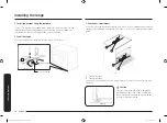
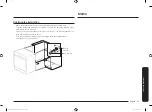
Page 13: ...suffer serious injuries caused by spilled hot liquids or by the range itself approximately 21 32 16 5 mm Screw must enter wood or concrete Anti Tip bracket NOTE To install the Anti Tip bracket release the leveling leg A minimum clearance of 21 32 16 5 mm is required between the range bottom and the kitchen floor Step 5 Replacing the access cover To replace the rear access cover on the range back I...

Page 14: ...ise range Lower range 3 Check your adjustments Use a spirit level to check your adjustments Place the level diagonally on the oven rack or surface cooktop and confirm the range is level in the two directions shown below 1 Check direction 1 2 Check direction 2 If the spirit level indicates that the range is not level adjust the leveling legs with a wrench Ground CAUTION For your safety do not attem...

Page 15: ...e rear left or rear right leg slides under the Anti Tip bracket Carefully tip the range forward to insure that the Anti Tip bracket engages the back brace and prevents tip over Turn on the electrical power Check the range for proper operation as described in the user manual Anti Tip bracket Leveling leg Memo Install_NE63T8911_AA_DG68 01257A 00_EN indd 15 2020 03 26 6 27 52 ...

Page 16: ...s to explain product operation correct improper installation or perform normal cleaning or maintenance QUESTIONS OR COMMENTS COUNTRY CALL OR VISIT US ONLINE AT U S A Consumer Electronics 1 800 SAMSUNG 726 7864 www samsung com us support CANADA 1 800 SAMSUNG 726 7864 www samsung com ca support English www samsung com ca_fr support French DG68 01257A 00 Install_NE63T8911_AA_DG68 01257A 00_EN indd 16...

Page 17: ...Estufa eléctrica Manual de instalación NE63 8 Install_NE63T8911_AA_DG68 01257A 00_MES indd 1 2020 03 26 6 27 38 ...

Page 18: ...ño o un adulto podrían inclinar la estufa y morir B Instale el dispositivo anti inclinación en la estructura y o en la parte posterior derecha o posterior izquierda de la base de la estufa C Acople la estufa en el dispositivo anti inclinación nivelando las patas en la parte posterior derecha o posterior izquierda de la base de la estufa D Vuelva a acoplar el dispositivo anti inclinación en caso de...

Page 19: ...VERTENCIA Si la información de este manual no es seguida con exactitud se podrían producir incendios o descargas eléctricas que causen daños a la propiedad lesiones personales o la muerte Antes de comenzar la instalación corte la alimentación eléctrica desde el panel de servicio y cierre con llave el interruptor de desconexión del servicio para evitar que la corriente eléctrica sea conectada accid...

Page 20: ...máxima admisible para gabinetes de madera de 194 F Asegúrese de que los revestimientos de paredes superficies de mesada y gabinetes alrededor de la estufa puedan soportar el calor hasta 194 F generado por la estufa De lo contrario se podrían producir alteraciones de color deslaminación o derretimiento A B 36 363 4 293 4 267 16 491 4 2811 16 2915 16 357 8 25 24 6 3 24 3 A Abertura del gabinete mín ...

Page 21: ...des laterales de la mesada Kit de relleno trasero opcional Se usa para llenar el espacio entre la parte trasera de la estufa y la pared Agrega una tira de relleno a la parte trasera de la estufa Este kit solo puede usarse cuando la abertura en la mesada tiene una profundidad de 25 1 Desatornille los tornillos que fijan la tapa de ventilación 2 Ensamble la tira de relleno a la parte posterior de la...

Page 22: ...anzar elementos por encima de las unidades de superficie calientes evite colocar gabinetes de almacenamiento arriba de las unidades de superficie Si tiene gabinetes de almacenamiento sobre los elementos calentadores puede reducir el riesgo instalando una campana para estufas que sobresalga horizontalmente como mínimo 5 pulgadas con respecto al extremo inferior de los gabinetes 30 30 15 Se requiere...

Page 23: ...s no existentes en ese momento para estufas de cocina se utilicen conexiones de cuatro conductores Cuando instale una estufa eléctrica en una construcción nueva siga los Pasos 2 y 3 para una conexión de 4 conductores Debe usar un sistema eléctrico de 3 o 4 conductores monofásico CA Sistema eléctrico de 208Y 120 voltios o 240 120 voltios 60 hertz Si el servicio eléctrico provisto no cumple con las ...

Page 24: ...ación de estufa watts Especificaciones del kit de cable para alimentación eléctrica y de la protección de circuito en amperes Diámetro en pulgadas de la abertura para conexión de la estufa 120 240 voltios 3 conductores 120 208 voltios 3 conductores Cable de alimentación Conducto 8750 16500 7801 12500 40 o 50 A 13 8 11 8 Este electrodoméstico debe ser alimentado con el voltaje y la frecuencia corre...

Page 25: ... El conductor neutral o de tierra del cable de alimentación debe conectarse a la terminal neutra ubicada en el centro del cuerpo de terminales Los chicotes de cable que portan corriente deben conectarse a las terminales inferior izquierda e inferior derecha del cuerpo de terminales 1 Retire los tornillos de las tres terminales inferiores del cuerpo de terminales 2 Introduzca los 3 tornillos termin...

Page 26: ...tierra y guárdelos 2 Corte y descarte la cinta de conexión a tierra No descarte ningún tornillo 3 Introduzca el tornillo de tierra en la terminal de aro de tierra del cable de alimentación a través de la chapa de conexión a tierra y dentro del marco de la estufa 4 Introduzca los 3 tornillos terminales retirados anteriormente a través de cada aro terminal del cable de alimentación y dentro de las t...

Page 27: ...onductores según se describe a continuación El conductor utilizado la ubicación y el encapsulamiento de uniones etc deben cumplir con las buenas prácticas de cableado y los códigos locales 1 Afloje los tornillos de las 3 terminales inferiores del cuerpo de terminales 2 Introduzca la punta desnuda del conductor central blanco neutro a través de la abertura en la parte central inferior del cuerpo de...

Page 28: ...e la punta desnuda del conductor de tierra entre el marco de la estufa y la chapa de conexión a tierra retirados anteriormente y fíjelo en su lugar con el tornillo de conexión a tierra 4 Introduzca la punta desnuda del conductor blanco neutro a través de la abertura en la parte central inferior del cuerpo de terminales 5 Introduzca las puntas desnudas de los dos conductores laterales en las abertu...

Page 29: ...s graves causadas por el derrame de líquidos calientes o por la estufa misma aproximadamente 21 32 16 5 mm El tornillo debe introducirse en madera o concreto Ménsula anti inclinación NOTA Para instalar la ménsula anti inclinación libere la pata niveladora Se requiere una distancia mínima de 21 32 16 5 mm entre la parte inferior de la estufa y el piso de la cocina Paso 5 Colocación de la cubierta d...

Page 30: ...trole sus ajustes Utilice un nivel de burbuja de aire para controlar los ajustes Coloque el nivel diagonalmente sobre la rejilla del horno o la superficie de cocción y confirme que la estufa está nivelada en las dos direcciones mostradas a continuación 1 Controle en la dirección 1 2 Controle en la dirección 2 Si el nivel de burbuja indica que la estufa no está nivelada ajuste las patas de nivelaci...

Page 31: ...a derecha se deslice por debajo de la ménsula anti inclinación Con cuidado incline la estufa hacia adelante para verificar que la ménsula Anti Inclinación engancha al puntal trasero e imposibilita el vuelco Encienda la corriente eléctrica Controle el funcionamiento correcto de la estufa tal como se describe en el manual del usuario Ménsula anti inclinación Pata niveladora Notas Install_NE63T8911_A...

Page 32: ...ra explicar el funcionamiento del producto corregir una instalación inadecuada o realizar tareas de limpieza o mantenimiento TIENE PREGUNTAS O COMENTARIOS PAÍS LLAME AL O VISÍTENOS EN LÍNEA EN U S A Consumer Electronics 1 800 SAMSUNG 726 7864 www samsung com us support CANADA 1 800 SAMSUNG 726 7864 www samsung com ca support English www samsung com ca_fr support French DG68 01257A 00 Install_NE63T...

Page 33: ...Cuisinière électrique Manuel d installation NE63 8 Install_NE63T8911_AA_DG68 01257A 00_CFR indd 1 2020 03 26 6 27 28 ...

Page 34: ...es ou des enfants risqueraient de faire basculer la cuisinière et d être tués B Installez le dispositif anti basculement sur la structure et ou sur la cuisinière à l arrière droite ou arrière gauche du dessous de l appareil C Emboîtez la cuisinière sur le dispositif anti basculement à l aide du pied de mise à niveau situé à l arrière droite ou arrière gauche du dessous de l appareil D Emboîtez à n...

Page 35: ...isinière ne doit pas être placée sur un socle Pour votre sécurité AVERTISSEMENT Si vous ne respectez pas scrupuleusement les informations contenues dans ce manuel vous risquez de provoquer un incendie ou un choc électrique et par conséquent des dégâts matériels blessures ou accidents mortels Avant de commencer l installation coupez l alimentation au panneau de commande et verrouillez l interrupteu...

Page 36: ...mpérature maximale autorisée pour tout meuble en bois Assurez vous que le revêtement mural les plans de travail et les meubles adjacents peuvent résister à la chaleur jusqu à 194 F générée par la cuisinière Dans le cas contraire des éléments peuvent se décolorer se décoller ou fondre A B 36 363 4 293 4 267 16 491 4 2811 16 2915 16 357 8 25 24 6 3 24 3 A ouverture du meuble minimum 30 76 2 cm B emp...

Page 37: ... moins 3 entre le découpage et les arêtes latérales du plan de travail Kit de fileur arrière en option Utilisez ce kit pour combler le jeu entre l arrière de la cuisinière et le mur Ajoute une baguette à l arrière de la cuisinière Ce kit ne peut être utilisé que lorsque la profondeur de l ouverture dans le plan de travail est de 25 1 Dévissez les vis maintenant la grille de ventilation en place 2 ...

Page 38: ... tout risque de brûlure ou d incendie lors de l accès à l espace situé au dessus des éléments de cuisson chauds évitez d y aménager tout meuble de rangement Si un meuble de rangement est situé au dessus des éléments de cuisson vous pouvez réduire le risque en installant une hotte d aspiration assurant une protection horizontale d au moins 5 pouces au delà du dessous du meuble 30 30 15 Un dégagemen...

Page 39: ...e vous installez une cuisinière électrique dans une construction neuve suivez les étapes 2 et 3 relatives à un raccordement à 4 fils Vous devez utiliser un système électrique à 3 fils ou 4 fils monophasé CA de 208Y 120 volts ou 240 120 volts 60 hertz Si votre installation électrique n est pas conforme aux spécifications ci dessus contactez un électricien agréé afin d installer une prise homologuée...

Page 40: ...s nominales spécifiées du kit de cordon d alimentation et de la protection de circuit ampères Diamètre pouces de l ouverture de connexion de la cuisinière 120 240 volts 3 fils 120 208 volts 3 fils Cordon d alimentation Gaine 8750 à 16500 7801 à 12500 40 ou 50 A 13 8 11 8 Cet appareil doit être alimenté par une tension et à une fréquence adaptées Il doit également être branché sur un circuit de dér...

Page 41: ...ise de terre ou la prise neutre du cordon d alimentation doit être connectée à la borne neutre située au centre du bornier Les câbles d alimentation doivent être connectés aux bornes inférieures gauches et inférieures droites du bornier 1 Retirez les 3 vis de la borne inférieure du bornier 2 Insérez les 3 vis de la borne dans les bornes inférieures du bornier en passant par chacun des anneaux de l...

Page 42: ...et jetez le conducteur de terre Ne jetez aucune vis 3 Insérez la vis de terre dans l anneau de la borne du fil de mise à la terre du cordon d alimentation en passant par la plaque de masse puis dans le bâti de la cuisinière 4 Insérez les 3 vis de la borne retirées précédemment dans les bornes inférieures du bornier en passant par chacun des anneaux de la borne du cordon d alimentation Assurez vous...

Page 43: ...sité et de la tension nominales correctes Raccordez les fils comme décrit ci dessous Le fil utilisé l emplacement les boîtiers d épissures etc doivent être conformes aux bonnes pratiques de câblage et aux codes locaux 1 Desserrez les 3 vis des bornes inférieures du bornier 2 Insérez l extrémité du fil dénudé blanc neutre central dans l ouverture inférieure centrale du bornier Sur certains modèles ...

Page 44: ...l extrémité du fil de terre dénudée entre le bâti de la cuisinière et la plaque de terre retirée précédemment et fixez la à l aide de la vis de terre retirée précédemment 4 Insérez l extrémité dénudée du fil blanc neutre dans l ouverture inférieure centrale du bornier 5 Insérez les deux extrémités dénudées des fils de chaque côté dans les ouvertures inférieure gauche et inférieure droite du bornie...

Page 45: ...res suite au renversement de liquides chauds ou de la cuisinière elle même approximativement 21 32 16 5 mm La vis doit pénétrer dans le bois ou le béton Support anti basculement REMARQUE Desserrez le pied de mise à niveau pour installer le support anti basculement Un dégagement d au moins 21 32 16 5 mm est nécessaire entre le dessous de la cuisinière et le sol de la cuisine Étape 5 remise en place...

Page 46: ...sinière Abaissement de la cuisinière 3 Vérification des réglages Utilisez un niveau à bulle pour vérifier vos réglages Placez le niveau en diagonale sur la grille du four ou la table de cuisson et vérifiez le niveau dans les deux directions indiquées ci dessous 1 Vérifiez la direction 1 2 Vérifiez la direction 2 Si le niveau à bulle indique que la cuisinière n est pas de niveau ajustez les pieds d...

Page 47: ...glisse sous le support anti basculement Inclinez avec précaution la cuisinière vers l avant afin de vous assurer que le support anti basculement s emboîte dans la fixation arrière et que la cuisinière ne bascule pas Mettez l appareil sous tension Vérifiez que la cuisinière fonctionne correctement comme indiqué dans le manuel d utilisation Support anti basculement Pied de mise à niveau Notes Instal...

Page 48: ...vente pour expliquer le fonctionnement de l appareil corriger une installation non correcte ou exécuter des travaux de nettoyage ou d entretien réguliers UNE QUESTION UN COMMENTAIRE PAYS N DE TÉLÉPHONE SITE INTERNET U S A Consumer Electronics 1 800 SAMSUNG 726 7864 www samsung com us support CANADA 1 800 SAMSUNG 726 7864 www samsung com ca support English www samsung com ca_fr support French DG68 ...

Reviews: