background image

ENGLISH-6

Installing the ERV wired remote controller

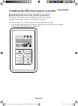
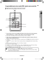
Installation procedure

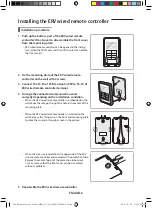
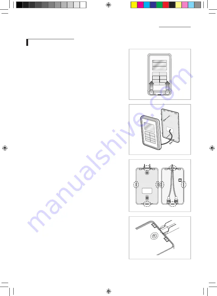
1.  Push up the bottom part of the ERV wired remote 

controller's front cover to disassemble the front cover 

from the mounting plate.


ū ERV wired remote controller can be opened in the sliding 

way . (Hold the front cover and then lift it up to disassemble 

the front cover .)

2.  Fix the mounting plate of the ERV wired remote 

controller on the wall with 2 screws.

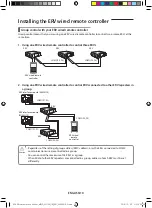
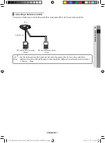
3.  Connect the F3, F4 of PCB terminal in ERV to F3, F4 of 

ERV wired remote controller terminal.

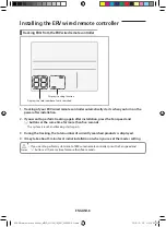
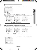
4.  Arrange the connected communication wires 

correctly depending on the installation condition.


ū When the ERV wired remote controller is embedded on the 

wall: Make the wire go through the hole in the center of the 

mounting plate .


ū When the ERV wired remote controller is installed on the 

wall: Remove the thin parts on the front and mounting plate 

to make the wires go through as seen in the picture .


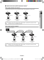
ū When the wire is extended from the upper side of the ERV 

wired remote controller and covered with a protection tube: 

Remove the contact point of the protection tube about 

1 cm or more so that the front cover can be assembled 

without a problem .

5.  Reassemble the ERV wired remote controller.

INSTALLATION

ERV Wired remote controller_MWR_VH12N_IM_EN_05309A-00.indd   6

2016-12-23   오후 6:02:53

Summary of Contents for ERV

Page 1: ...troller MWR VH12N ERV Energy Recovery Ventilator installation manual imagine the possibilities Thank you for purchasing this Samsung product ERV Wired remote controller_MWR_VH12N_IM_EN_05309A 00 indd...

Page 2: ...stalling ERV wired remote controller 5 INSTALLATION Installing the ERV wired remote controller 6 Using installation service mode of ERV wired remote controller 15 Contents ERV Wired remote controller_...

Page 3: ...se or a contact center to disassemble or repair the product f f Potential risk of malfunction electric shock or fire The electric work must be done by qualified person according to national wiring reg...

Page 4: ...hock or product damage Do not install the product in areas exposed to oil or vapor f f Potential risk of product damage or malfunction Do not put undue stress on the power cable f f Potential risk of...

Page 5: ...lled by an installation expert Check and confirm the power is off before installing ERV wired remote controller Install the ERV wired remote controller cables in accordance with the electrical wiring...

Page 6: ...ed communication wires correctly depending on the installation condition When the ERV wired remote controller is embedded on the wall Make the wire go through the hole in the center of the mounting pl...

Page 7: ...ote controller by using two pieces of PVC wire remove the 30 cm of the sheath of the cable and install it only with the two pieces of wires Recommended specification AWG21 The followings are the specs...

Page 8: ...tallation press the Fan speed and buttons at the same time for more than five seconds The system is reset and tracking starts again 3 During the tracking the total number of currently searched product...

Page 9: ...g of group address RMC address only the ERV connected to COM2 communication wire is individually controlled Caution When a upper controller is connected CN4 CN3 RED CN2 BLK ERV interface module MIM N1...

Page 10: ...Vs connected to other ERV repeaters in a group CN4 CN3 RED CN2 BLK CN4 CN3 RED CN2 BLK ERV interface module MIM N10 ERV ERV ERV wired remote controller ERV interface module MIM N10 COM1 F1 F2 COM2 F3...

Page 11: ...ed remote controller Master COM2 F3 F4 ERV wired remote controller Slave For the setting of slave ERV wired remote controller please refer to the sections about the additional functions of the ERV wir...

Page 12: ...changes When the number of ERVs indoor units or their address is changed Press the Fan speed and buttons at the same time for more than five seconds f f Your ERV wired remote controller is initialized...

Page 13: ...ecimal number Indoor unit Outdoor unit address Hexadecimal Number Indoor unit address Hexadecimal Number When an error occurs in ERVs or ERV repeaters Product Group Display b30 f f The product address...

Page 14: ...led devices Error on installation of slave ERV wired remote controller When more than 2 slave ERV wired remote controllers are installed Communication error between master ERV wired remote controller...

Page 15: ...n menu number and press the Away button to enter the sub menu setting screen f f Using the buttons select a sub menu number and press the Away button to enter data setting screen f f When you enter th...

Page 16: ...EA 3 Checking the Micom code of ERV wired remote controller none 3 Micom code 4 Checking the program version information of ERV wired remote controller none 3 Modified date 2 1 Setting address option...

Page 17: ...ng optional functions of ERV wired remote controller ERV wired remote controller Master Slave 0 1 0 Master 1 Slave 2 Use of external interlock 0 1 0 Disuse 1 Use 5 1 Setting checking ERV Exhaust RPM n...

Page 18: ...splayed can be distinguished by operation mode On and Off icon SEG2 SEG6 SEG8 SEG12 On Heat EX By Pass Auto Quiet Away SEG14 SEG18 SEG20 24 Off Heat EX By Pass Auto Quiet Away SEG 2 3 PAGE 1 PAGE 6 PA...

Page 19: ...66 03 3 13 19 23 35 33 51 43 67 04 4 14 20 24 36 34 52 44 68 05 5 15 21 25 37 35 53 45 69 06 6 16 22 26 38 36 54 46 70 07 7 17 23 27 39 37 55 47 71 08 8 18 24 28 40 38 56 48 72 09 9 19 25 29 41 39 57...

Page 20: ...set on the sub menu f f Press the or button to select no 1 3 Press the Away button to enter the data setting stage f f When you enter the setting stage the current setting is displayed 4 Press the or...

Page 21: ...ENGLISH 21 02 INSTALLATION Memo ERV Wired remote controller_MWR_VH12N_IM_EN_05309A 00 indd 21 2016 12 23 6 02 57...

Page 22: ...ERV Wired remote controller_MWR_VH12N_IM_EN_05309A 00 indd 2 2016 12 23 6 02 52...

Reviews: