background image

CN01  

Door Plunger  
Door Lock Switch 


CN11 

Comm to CN604


CN02                          

Oven Sensor 


CN05 

Connector 

to Sub PCB Ass’y 
CN602


CN07 

15 pin 

ribbon connector 
to Keypad


CN04 

Connector 

to Sub PCB Ass’y 
CN603  


CN10 

LV Transformer 

Red~Red (13.5vac) 1.5~2.5


Yellow~Yellow (8vac) 0.8~1.5


CN08 

LV Transformer 

Primary (120vac) 75~80


CN09 

120vac supply


CN502 

Induction & Hot 

Surface Lamps


CN501 

Temp 

Protector


RY603 

Broil 

Relay 


RY604 

Bake 

Relay 


RY602 

Double Line 

Break Relay  


CN601                  

Oven Lamp           
Conv. Fan                  
Door Switch   


RY608 

Warm 

Relay


RY405 

Source 

Relay


CN602


To CN05


CN204  

Inverter 

PCB Comm line


CN301             

DC Fan Mtr


CN101     


120 VAC


CN203


RF Induction Top 
Sensor


RY607 

Conv. 

Relay


CN603              

To CN04


CN604 

Comm    

To CN11 


CN205         

To Touch PCB


RY401 

Source 

Relay 


3

Summary of Contents for FE-N300WX/XAA

Page 1: ... wire harness identical to the way they were to prevent electromagnetic interference causing possible fault codes Induction Burner Radiant Burners Inverter PCB Power PCB Main PCB Inverter Coil Touch Pad PCB Component Voltage Wattage Resistance Room Temp Component Voltage Wattage Resistance Room Temp LR Rad 240vac 1200W 45Ω 50Ω Broil 240vac 3800 W Approx 13 16Ω RF I 240vac 9 2200 3200W 0 01 1Ω Bake...

Page 2: ...2 ...

Page 3: ...8 1 5Ω CN08 LV Transformer Primary 120vac 75 80Ω CN09 120vac supply CN502 Induction Hot Surface Lamps CN501 Temp Protector RY603 Broil Relay RY604 Bake Relay RY602 Double Line Break Relay CN601 Oven Lamp Conv Fan Door Switch RY608 Warm Relay RY405 Source Relay CN602 To CN05 CN204 Inverter PCB Comm line CN301 DC Fan Mtr CN101 120 VAC CN203 RF Induction Top Sensor RY607 Conv Relay CN603 To CN04 CN60...

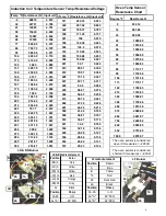
Page 4: ... 74 0 241 482 47 36 0 226 491 44 26 0 212 500 41 42 0 199 509 38 81 0 187 518 36 41 0 176 527 34 2 0 165 536 32 16 0 156 545 30 28 0 147 554 28 54 0 139 563 26 92 0 131 572 25 43 0 124 Temp o F Resistance Ω Input volt Degree ºF Resistance Ω 0 932 12 14 961 86 23 980 95 32 1000 00 41 1019 02 50 1038 02 59 1056 99 68 1075 92 77 1094 83 86 1113 71 95 1132 56 104 1151 38 113 1170 17 122 1188 93 212 13...

Page 5: ...r Oven Main PCB Touch Control PCB Check wire harness connection between Oven main PCB and Touch control PCB If there is no problem with connector or wire replace the Oven main PCB or Touch control PCB E 56 Warning error When Cooktop part has some error Refer to Cooktop Failure Display Codes section FL DC Motor Locking Error It occurs when the DC Motor cannot operate due to defects of PCB wiring or...

Page 6: ... Touch PCB Door Lock Error Press and hold Cook Time Delay Start for 3 seconds to test motor operation No Burner operation Check relay terminal for 240vac Check wiring from Inverter PCB to Touch PCB Remove power Check resistance between G E G C E C any short replace Inverter PCB Pan Detection Error Verify proper pans being used Check wiring from Inverter PCB to Touch PCB wiring is OK Replace Ass y ...

Reviews: