46
4. Troubleshooting
4-1 Failure Display Codes
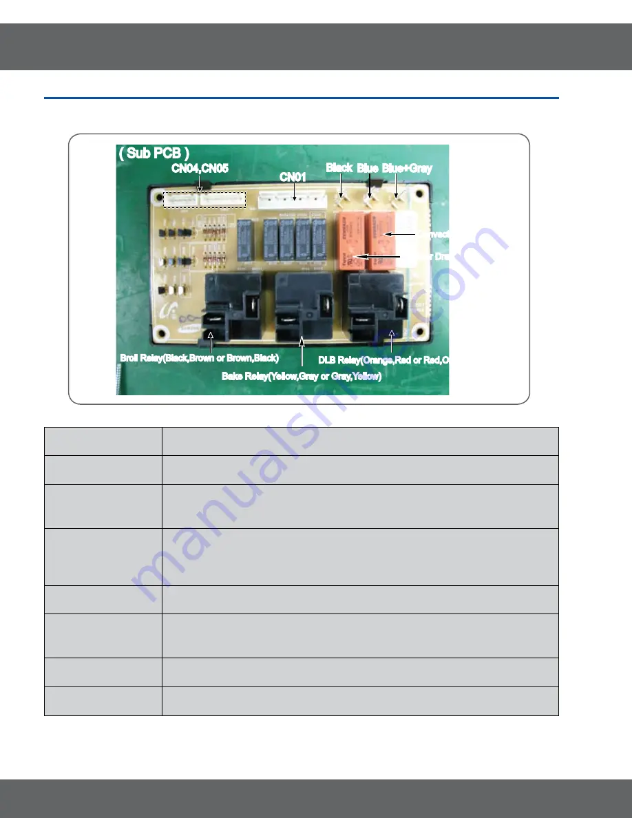
Explain primary parts of Sub PCB
Bake Relay(Yellow,Gray or Gray,Yellow)
Bake Relay(Yellow,Gray or Gray,Yellow)
CN01
CN01
Broil Relay(Black,Brown or Brown,Black)
Broil Relay(Black,Brown or Brown,Black)
CN04,CN05
CN04,CN05
( Sub PCB )
( Sub PCB )
DLB Relay(Orange,Red or Red,Orange)
DLB Relay(Orange,Red or Red,Orange)
Black
Black
Blue
Blue
Blue+Gray
Blue+Gray
Warmer Drawer Relay
Warmer Drawer Relay
Convection Relay
Convection Relay
Explatin of the function of primary parts .
CN01
This is connector which have Door plunger switch, cooktop warming center, oven
lamp and relay of convection fan connected .
CN04,CN05
Connector(CN04,CN05) on sub PCB take a role of getting all of the operation of
relay on sub PCB to connect with main PCB(CN04,CN05) .
DLB relay(Ry02)
Circuit is designed to have broil relay or convection relay worked after DLB relay is
being worked by Double line break .
(It will not be problem with reversing the order in insering Orange and Red)
Broil relay(Ry03),
Bake relay(Ry04),
convection relay(Ry05)
Broil relay(Ry03), Bake relay(Ry04), convection relay(Ry05) will be on-off working
by micom signal after DLB relay is worked .
(Broil relay : It will not be problem with reversing the order in insering Black and Brown)
(Bake relay : It will not be problem with reversing the order in insering Yellow and Gray)
Ry-source relay(Ry01) This is consisted of 15 pin and take a role of getting a cable on keypad to connect
with touch PCB .
W/Drawer Relay(Ry06)
and T03 terminal
This is terminal to connect harness with relay to get heater on warming drawer work .
T02 terminal
This is the terminal to connect convection heater with convection relay .
T01 terminal
This is the terminal to supply L1 voltage(120V) with warming drawer
relay(Ry06),convection relay(Ry05) .


