38
4. Troubleshooting
4-1 Failure Display Codes
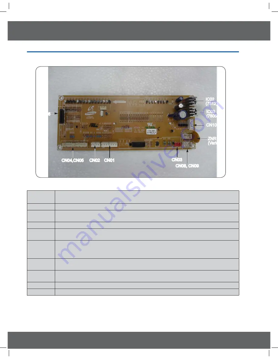
* Explain of primary parts of Main PCB
IC03
(7805)
IC02
(7812)
CN10
ZNR1
(Varistor)
CN03
CN03
CN01
CN01
CN02
CN02
CN04,CN05
CN04,CN05
CN06
CN06
CN08, CN09
CN08, CN09
IC03
(7805)
IC02
(7812)
CN10
ZNR1
(Varistor)
Explatin of the function of primary parts.
CN01
This is connector which is connected with Door plunger switch and Door lock switch.
(COM-NO)
CN02
This is connector which is connected with oven sensor.
CN03
This is to stop operating self-cleaning and steam mode if hot indicator lamp on cooktop is
lighted with being supplied with AC120V(L1, N).
CN04,CN05
This connector is to get all operating of relay on sub PCB to be connected.
CN06
This is consisted of 15 pin and take a role of getting a cable on keypad to connect with touch
PCB.
CN08,CN09
This is to supply power with primary on Low voltage transformer, and AC120V with main PCB
through harness.
It won
t be problem even though CN08 and CN09 has been changed when you insert housing.
CN10
This is connector which take a role of supplying secondary voltage of Low voltage transformer
with main PCB.
ZNR1
This is the element to protect main PCB, getting varistor to work if over voltage is supplied with
varistor.
IC02
This is to supply DC12V with main PCB by voltage regulator.
IC03
This is to supply DC5V with main PCB by voltage regulator.
1(5$%65B$$LQGE


