background image

MICROWAVE OVEN

FEATURES

Refer to the service manual in http://itself.sec.samsung.co.kr for more information.

1.  Competitive cost .
2.  Great cooking performance.

BASIC: 

GR87

MODEL: 

G2739NR

MODEL CODE: G2739NR-D/BWT


G2739NR-SD/BWT

Summary of Contents for G2739NR

Page 1: ...E OVEN FEATURES Refer to the service manual in http itself sec samsung co kr for more information 1 Competitive cost 2 Great cooking performance BASIC GR87 MODEL G2739NR MODEL CODE G2739NR D BWT G2739NR SD BWT ...

Page 2: ... Samsung Electronics Co Ltd January 2006 Printed in Korea Code No DE68 04055A ...

Page 3: ...ron 12 5 4 High Voltage Capacitor 13 5 5 High Voltage Diode 13 5 6 Main Relay and Power Control RelayA 13 5 7 Adjustment of Primary Switch Door Sensing Switch and Monitor Switch 13 5 8 Output Power of Magnetron 14 5 9 Microwave Heat Distribution Heat Evenness 14 5 10 Procedure for Measurement of Microwave Energy Leakage 15 5 11 Check for Microwave Leakage 15 5 12 Note on Measurement 15 5 13 Leakag...

Page 4: ...ges and latches 5 evidence of dropping or abuse c Before turning on microwave power for any service test or inspection within the microwave generating compartments check the magnetron wave guide or transmission line and cavity for proper alignment integrity and connections d Any defective or misadjusted components in the interlock monitor door seal and microwave generation and transmission systems...

Page 5: ...rlock Monitor Switch Replace all of the following at the same time Primary door sensing switch and power relay as well as the Interlock Monitor Switch The correct adjustment of these switches is described elsewhere in this manual Make sure that the fuse has the correct rating for the particular model being repaired 13 Design Alteration Warning Use exact replacement parts only i e only those that a...

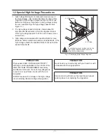
Page 6: ...stments If the high voltage exceeds the specified limits check each of the special components H V Diode H V Capacitor Short Touch chassis ground first then short to the high voltage capacitor terminal by using screwdriver or jumper wire Fig 1 1 Discharging High Voltage Capacitor PRECAUTION There exists HIGH VOLTAGE ELECTRICITY with high current capabilities in the circuits of the HIGH VOLTAGE TRANS...

Page 7: ...able Door open Method Handle Handle Oven Tray Glass 288 mm Glass 318 mm Oven Material Epoxy Epoxy Control Method Membrane Tact Display LCD LED Bar Power Levels 4 levels 6 levels Weight Net 15 kg 14 5 kg Weight Gross 16 5 kg 16 kg Loading Q ty 40ft 755 Sets 40ft 576 Sets 40ft Power Source 230V 50Hz 230V 50Hz Input Power 1100 W 1200 W Output Power 750 W 800 W Heater Power 950 W 800 W Cooking Time 99...

Page 8: ...LAY 2 INSTANT REHEAT COOK SELECTION 3 AUTO DEFROST FEATURE SELECTION 4 WEIGHT SELECTION 5 MICROWAVE MODE SELECTION 6 GRILL MODE SELECTION 7 STOP CANCEL BUTTON 8 COMBI MODE SELECTION 9 CLOCK SETTING 10 TIME SETTING 11 START BUTTON 1 2 3 4 5 6 7 8 9 10 11 ...

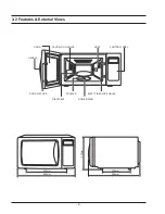
Page 9: ... 6 3 2 Features External Views 489mm 330mm 396mm 320mm 275mm DOOR HANDLE DOOR LATCHES VENTILATION HOLES LIGHT CONTROL PANEL TURNTABLE COUPLER ROLLER RING SAFETY INERLOCK HOLES ...

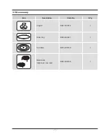
Page 10: ... 7 3 3 Accessory Item Description Code No Q ty Coupler DE87 00187A 1 Roller ring DE92 90189T 1 Turntable DE74 20015G 1 Metal racks High rack Low rack DE97 00216E 1 ...

Page 11: ... that its antenna does not hit any adjacent parts or it may be damaged NOTE2 When replacing the magnetron be sure to remount the magnetron gasket in the correct position and make sure the gasket is in good condition 4 2 Replacement of High Voltage Transformer 1 Discharge the high voltage capacitor 2 Disconnect all the leads 3 Remove the mounting bolts 4 Reconnect the leads correctly and firmly PREC...

Page 12: ...oor E Door A Door C Door E Key Door Spring Door E 4 3 2 Removal of Door E Following the procedure as shown in the figure insert and bend a thin metal plate between Door E and Door A until you hear the tick sound Insertion depth of the thin metal plate should be 0 5mm or less Door A Door C Door E Key Door Spring Door E 4 3 3 Removal of Key Door Spring Remove pin hinge from Door E Detach spring from ...

Page 13: ...he operation of interlock monitor switch failure replace the primary interlock switch door sensing switch monitor switch and power relay 3 When the above three switches operate properly check if any other part such as the control circuit board blower motor or high voltage transformer is defective 4 5 Replacement of Drive Motor 1 Take out the glass tray guide roller from oven cavity disconnect powe...

Page 14: ...from the Ass y control box 4 When reconnecting the FPC connector make sure that the holes on the connector are properly engaged with the hooks on the Plastic Fastener CONTROL BOX SCREWS SCREWS ASSY PCB Membrane Panel 4 6 3 Removal of Window Display Membrane Panel 1 Window display should not be disassembled as its mounting tabs will be broken If repair work is difficult replace with Ass y control pa...

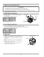
Page 15: ...Voltage Transformer 1 The low voltage transformer is located on the control circuit board 2 Remove the low voltage transformer from the PCB Ass y and check continuity 3 Normal resistor reading is shown in the table Terminals Resistance 1 2 Input 1250 Ω 3 4 Output7V 17 4 Ω 5 6 Output17V 3 53Ω 5 3 Magnetron 1 Continuity checks can indicate only an open filament or a shorted magnetron To diagnose an o...

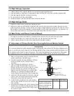
Page 16: ...iagram and be sure to use the correct part number for the following switches Primary and secondary interlock switches and the interlock monitor switch replace all together Then follow the adjustment procedures below After repair and adjustment be sure to check the continuity of all interlock switches and the interlock monitor switch 1 When mounting Primary switch and Interlock Monitor switch to La...

Page 17: ...55xMcx T2 T1 58 Heating Time sec 55 Counting Time sec 4 187 Coefficient for Water 1000 Water cc T Temperature Rise T2 T1 To Room Temperature Mc Cylindrical borosilicate glass weight 55 7 Normal temperature rise for this model is 9 C to 11 C at HIGH NOTE 1 Variations or errors in the test procedure will cause a variance in the temperature rise Additional power test should be made if temperature rise...

Page 18: ...a beaker which is graduated to 600cc and place the beaker in the center of the oven 3 Start the oven at the highest power level 4 Set survey meter dual ranges to 2 450MHz 5 Using the survey meter and spacer cone as described above measure near the opening of magnetron the surface of the air guide and the surface of the wave guide as shown in the following photo but avoid the high voltage component...

Page 19: ...ormer NOTE 2 Check adjustment of primary interlock monitor power relay door sensing switch NOTE 1 All of these switches must be replaced at the same time refer to adjustment instructions Check continuity of power relay contacts and if it has continuity replace power relay also NOTE 2 When H V Transformer is replaced check diode and magnetron also Oven does not accept key input Program 1 Key input ...

Page 20: ... main Loud buzzing noise can be heard 1 Loose fan and fan motor 2 Loose screws on H V Transformer 3 Shorted H V Diode Tighten screws of fan motor Tighten screws of H V Transformer Replace H V Diode Turntable motor does not rotate 1 Open or loose wiring of turntable motor 2 Defective turntable motor Replace turntable motor Oven stops operation during cooking 1 Open or loose wiring of primary interl...

Page 21: ...al Inspection method Make sure to inspect the power relay after replacing primary interlock switch secondary interlock switch and door sensing switch Primary interlock switch Secondary interlock switch Door sensing switch Latch switch assembly Replace Relay Check a fan motor after replacing switch Check PCB after replacing L V T Power Point Check Point In case any of high voltage parts is damaged ...

Page 22: ...Switch Connector Door Key Securing nuts Door open Door closed 1 Loosenly tighten the nuts to check whether the primary interlock switch works by slightly moving latches to right and left Then firmly tighten nuts 2 Check whether the secondary interlock switch and door sensing switch work by slightly moving latches to right and left then firmly tighten nuts Tact Type Membrane Type Method to control ...

Page 23: ... No 1 and No 2 refer to Open Error not sensed and Short Error respectively 4 For unusual cases errors can be indicated in letters after discussion in advance ex Key Short Error SE 5 Error code not mentioned below should be discussed in advance and approved by P L and numbered reported to relevant departments 6 This numbering rule has been applied to models to have been developed since January 1 20...

Page 24: ...king by heater starts Weight Sensor Error Code Gas Sensor Error Case E 1X E 31 Open When value of HEX is above FF for 5 seconds E 32 Short E 33 In case the initial value of HEX is under 14 for 30 seconds while a weight sensor in operation E 34 In case the initial value of K calculated by a weight sensor is above and under 28 as value of HEX E 35 In case the value of A is as a weight sensor calcula...

Page 25: ...E 0X Letter SE Key Short Error 10 seconds E 01 The door opens in case the door should not be opened E 02 Cooking Time Setting Over Error MWO E 03 Cooking Time Setting Over Error Grill E 04 Cooking Time Setting Over Error Convection E 05 Cooking Time Setting Over Error Combination E 06 It fails to sense that the swing heater has stopped for 20 seconds during cooking E 08 In case function of MWO sta...

Page 26: ... M001 M003 M152 M151 M150 M012 C091 M030 M051 M031 M049 M095 W002 M015 M019 M022 M023 H018 B018 M036 M037 M035 H013 B002 B001 B010 B011 B006 M041 M040 M039 M038 M048 M047 M042 T030 T001 T017 M034 D049 D002 D003 D011 D007 C003 C005 C004 C082 C009 D004 D006 D005 ...

Page 27: ...2 SNA MAIN 1 1 M047 DE61 40066A FOOT PP BLK 2 SA MAIN B PLATE 1 1 M034 DE67 00140A COUPLER PPS ESS840 3G BRN NEW 1 SA MAIN 1 1 M001 DE70 00184A PANEL OUTER SECC T0 5 MW850WA 0 8 1 SA MAIN 1 2 M150 DE96 00155A ASSY HEATER COVER N7Q88 QUARTZ 1 SNA 1 3 M151 DE63 00076A COVER HEATER U N7Q88 ALSTAR T0 5 W160 L 1 SNA 1 3 M152 DE71 60353A COVER HEATER L STS304 T0 5 160 290 1 SA 1 1 M022 DE71 00148A COVER...

Page 28: ...DE67 00140A COUPLER PPS ESS840 3G BRN NEW 1 SA MAIN 1 1 M001 DE70 00184H PANEL OUTER NC 2000 SECC T0 5 SILVER 1 SA MAIN 1 1 M022 DE71 00148A COVER BLOWER PP T1 5NTR MW850WA NC2000 1 SA MAIN 1 1 M051 DE71 00151A COVER MGT PP T2 W54 L129 GE WHTMW850WA 1 SA MAIN 1 1 P186 DE71 60298A COVER BACK SECC T0 6 W273 L633 M6Q45 1 SA MAIN 1 1 M037 DE71 60457C COVER AIR 3RD 0 7 BTM PP FB53 G30 1 SA MAIN 1 1 T00...

Page 29: ...09 DE67 40179A WINDOW DISPLAY SAN T2 0 SMOG 3RD W 1 SA 1 2 C003 RCS N2LED1 39 ASSY PCB PARTS G2739NR 230V60HZ 1 SA G2739NR SD S N A SERVICE NOT AVAILABLE Level No Code No Description Specification Q ty SA SNA Remark 1 1 D049 DE94 00552K ASSY DOOR M1719N S XEU SILVER SILK TDS S 1 SA MAIN 1 2 D005 DE01 00112A FILM DOOR PET L268 T0 15 W150 NTR 1 SA 1 2 D007 DE61 00198A SPRING KEY M1877 HSWR D6 23 1 4 ...

Page 30: ...K 1 1 6006 001170 SCREW ASSY TAPP WS TH M4 L10 ZPC YEL 3 SNA PACKING P C EARTH 1 1 6006 001176 SCREW ASSY TAPT WT PH M4 L8 ZPC YEL 3 SNA PACKING MGT TCO 1 1 DE60 10051A SCREW TAP PH MSWR PH M4 L6 1 SNA MAIN D MOTOR 1 1 DE60 10080A SCREW WASHER M5 L12 2S 2 SA PACKING MGT 1 1 DE60 10082I SCREW A 2S 4X10 FEFZY 6 SNA MAIN O PANEL 1 1 DE60 30016A NUT FLANGE M4 MSWR10 1 SA PACKING F MOTOR 1 2 6002 00063...

Page 31: ... 28 8 Schematic Diagrams 8 1 Schematic Diagrams This Document can not be used without Samsung s authorization ...

Page 32: ...R13 1 4 2007 000346 R CHIP 120OHM 5 1 8W DA TP 3216 8 SNA R26 1 4 2007 000468 R CHIP 1Kohm 5 1 8W TP 2012 5 SNA R10 1 4 2007 000671 R CHIP 2Kohm 5 1 8W TP 2012 2 SNA R29 1 4 2007 000931 R CHIP 470ohm 5 1 8W TP 2012 1 SNA R06 1 4 2007 000941 R CHIP 47Kohm 5 1 8W TP 2012 6 SNA R32 1 4 2203 000444 C CER CHIP 1nF 10 50V X7R TP 2012 6 SNA C20 1 4 2203 000555 C CER CHIP 0 02NF 5 50V C0G TP 2012 2 SNA C1...

Page 33: ... 30 10 Wiring Diagrams 10 1 Wiring Diagrams This Document can not be used without Samsung s authorization ...

Page 34: ...This Document can not be used without Samsung s authorization MAGNETRON FA F RED RED RED RED SYMBOL COLOR BRN BROWN BLK BLACK RED RED BLU BLUE BLU BLK HIGH VOLTAGE TRANSFORMER HIGH VOLTAGE CAPACITOR HIGH VOLTAGE DIODE TO CHASSIS H V FUSE ...

Page 35: ...ION C RC USA RV CONVECTION BUILT IN B RB USA RV BUILT IN USA Junior SJ SJ USA Junior MWO USA OTR SM SOLO H SMH USA OTR SOLO CONVECTION V SMV USA OTR CONVECTION EUROPE Epoxy Cavity M SOLO 1 M1 EUROPE SOLO EPOXY CAVITY GRILL 2 M2 EUROPE GRILL EPOXY CAVITY EUROPE Ceramic Enamel CE SOLO 1 CE1 EUROPE SOLO CERAMIC ENAMEL GRILL 2 CE2 EUROPE GRILL CERAMIC ENAMEL EUROPE Quartz GRILL G2 G2 EUROPE Quartz GRI...

Page 36: ...DIUM LOW This function is used to cook the food slowly Close the door completely Press the Cancel button Press the Start button Contact the nearest Samsung after sales service center Ground Ground problem may happen when the oven is placed in a humid area and the over is not grounded Ground is not provided by an extended electric outlet If the oven is placed in a humid area buy an electric wire in...

Page 37: ...button However the smells produced from the food exposed such as herbal remedies are not removed Error Errors are classified into the case which is out of order and the case which is not out of order Clean the inside of the oven Remove strange smell through the Deodorant button If the strange smell still remains place a piece of lemon on the turntable and operate the oven for 5 minutes by pressing ...

Reviews: