background image

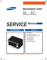
Refer to the service manual in the GSPN(see rear cover) for the more information.

1. Precaution

. Pro

G

uct S

S

eci

¿

cation

3.  Disassembly and Reassembly

4. Troubleshooting

5. PCB 

Diagrams

6. Wiring 

Diagrams

7. Schematic 

Diagrams

BASIC: 

GE73MR

MODEL: GE73M
MODEL CODE:  GE73M/XEO

0*0$(065B%:LQGE

Summary of Contents for GE73M

Page 1: ...SPN see rear cover for the more information 1 Precaution ProGuct SSeci cation 3 Disassembly and Reassembly 4 Troubleshooting 5 PCB Diagrams 6 Wiring Diagrams 7 Schematic Diagrams BASIC GE73MR MODEL GE73M MODEL CODE GE73M XEO 0 0 065B LQGE ...

Page 2: ...igh Voltage Trancefomer 10 3 3 Replacement of Door Assembly 12 3 4 Replacement of Drive Motor 13 3 5 Replacement of Control Circuit Board 14 3 6 Replacement of Heater 15 4 Troubleshooting 16 4 1 Parts checking method 16 4 2 Error Code Numbering Rule 17 4 3 Error Code List 17 4 4 Electrical Malfunction 19 5 PCB Diagrams 36 5 1 PCB Diagrams 36 5 2 PCB Diagrams 37 6 Wiring Diagrams 38 6 1 Wiring Diag...

Page 3: ...3 1 Precaution 0 0 065B LQGE ...

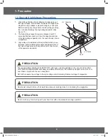
Page 4: ...ck Monitor Switch Replace all of the following at the same time Primary door sensing switch and power relay as well as the Interlock Monitor Switch The correct adjustment of these switches is described elsewhere in this manual Make sure that the fuse has the correct rating for the particular model being repaired 13 Design Alteration Warning Use exact replacement SDUWV RQO L H RQO WKRVH WKDW DUH VS...

Page 5: ...LQHG ZLWKLQ VSHFL HG OLPLWV E FORVH tolerance safety related components and adjustments If WKH KLJK YROWDJH H FHHGV WKH VSHFL HG OLPLWV FKHFN HDFK of the special components H V Diode Short H V Capacitor PRECAUTION There exists HIGH VOLTAGE ELECTRICITY with high current capabilities in the circuits of the HIGH 92 7 75 16 250 5 VHFRQGDU DQG ODPHQW WHUPLQDOV W LV H WUHPHO GDQJHURXV WR ZRUN RQ RU near...

Page 6: ... 50Hz AC 230V 50Hz AC Power consumption Microwave 1150W 1150W Grill 1100W 1100W Combi 2250W 2250W Output Power 100W 750W IEC 705 100W 750W IEC 705 Operating Frequency 2450MHz 2450MHz Cooling Method Cooling fan motor Cooling fan motor Dimensions W x H x D Outside 489 x 275 x 367mm 489 x 275 x 352mm Oven cavity 330 x 211 x 309mm 330 x 211 x 309mm Volume 20Liter 20Liter Weight Net 12 5Kg 12 5Kg Expor...

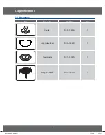
Page 7: ...7 2 Speci cations 2 3 Accessory Item Description Code No Q ty Coupler DE67 00258A 1 Assy Guide Roller DE94 02266D 1 Tray cooking DE74 00027A 1 Assy Wire Rack DE74 70071D 1 0 0 065B LQGE ...

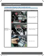
Page 8: ...l lead wires from the magnetron and lamp 2 Unfold the 2 pieces of small iron piece on the Cavity 3 Remove the air cover 3 1 Disassembly of Magnetron Motor Assembly and Lamp Remove the magnetron including the shield case permanent magnet choke coils and capacitors all of which are contained in one assembly 0 0 065B LQGE ...

Page 9: ...ion Magnetron Motor Assembly and Lamp 4 Remove screws securing the magnetron to the wave guide 5 Take out the magnetron very carefully 6 Remove two screws from the back panel 7 Take out the fan motor 3 1 Disassembly of Magnetron Motor Assembly and Lamp 0 0 065B LQGE ...

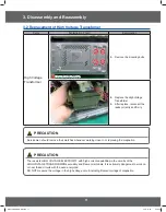
Page 10: ... any adjacent parts or it may be damaged NOTE2 When replacing the magnetron be sure to remount the magnetron gasket in the correct position and make sure the gasket is in good condition 3 2 Replacement of High Voltage Trancefomer Parts Explaination Photo Explaination High Voltage Transformer 1 Discharge the high voltage capacitor 2 Disconnect all the leads 3 1 Disassembly of Magnetron Motor Assemb...

Page 11: ...O DQG UPO PRECAUTION Servicemen should remove their watches whenever working close to or replacing the magnetron PRECAUTION There exists HIGH VOLTAGE ELECTRICITY with high current capabilities in the circuits of the 92 7 75 16 250 5 VHFRQGDU DQG ODPHQW WHUPLQDOV W LV H WUHPHO GDQJHURXV WR ZRUN RQ or near these circuits with the oven energized 2 127 PHDVXUH WKH YROWDJH LQ WKH KLJK YROWDJH FLUFXLW L...

Page 12: ...s fragile Then remove door assembly Removal of Door Assembly Lift up the Door Assembly from Cavity Removal of Door E Following the procedure as shown in the JXUH LQVHUW DQG EHQG D WKLQ PHWDO SODWH between Door E and Door A until you hear the tick sound Insertion depth of the thin metal plate should be 0 5mm or less Removal of Key Door Spring Remove pin hinge from Door E Detach spring from Door E a...

Page 13: ... sharp edge after cover removal 3 Disconnect leads from motor 4 Remove the screws securing motor to bottom of over cavity Drive Motor 6 Lift out the motor 5 When replacing the motor be sure to remount it in the correct position NOTE The shaft of motor should W WLS FRXSOHU COVER FIXING SCREW MATCHINE SCREW 6006 001170 6 When reassemble a drive motor cover give a turn in a DQG ZLWK D VFUHZ NOTE Brin...

Page 14: ...ard 3 Remove screws securing the control box assembly 4 Remove the screw securing the ground tail of the keyboard Removal of Ass y P C B Assembly and Assy Key Module ASSY PCB ASSY PCB ASSY KEY MODULE TAIL ASSY KEY MODULE TAIL SCREW SCREW SCREW SCREW SCREW SCREW 1 Remove 2 screws securing the Assy PCB 2 Remove Assy Key Module Tail from the Assy PCB 3 Lift up the Assy PCB from the Ass y control box ...

Page 15: ...ion Bracket Upper 1 Remove the Screw on Bracket upper Cover Blower Cover Blower Bracket Upper 2 Remove the screw Cover Blower and Bracket Upper Gasket 3 Remove the Nuts for disassemble the Gasket and lead Wire Stopper 4 Press the center of stopper with tools and move the stopper 0 0 065B LQGE ...

Page 16: ...eshooting 4 Troubleshooting 4 1 Parts checking method Parts Photo Good No Good Fuse a 0 H FHHG T C O a 0 H FHHG H V Trans a 0 H FHHG Convection a 0 H FHHG Fan Motor a 0 H FHHG Grill Heater a 0 H FHHG 0 0 065B LQGE ...

Page 17: ...e E 11 Open Check Sensor part connection of sensor housing and PCB s connector E 12 Short E 13 T1 Max Time Error E 14 Dry Up No Load Insert food and restart Temp Sensor Error Code Temp Sensor Error Case E 2X Solution Page E 21 Open Check sensor part and connection of sensor housing and PCB s connector E 22 Short E 23 T1 Max Time Error Preheating not completed Check heater E 24 Over temperature err...

Page 18: ...ror 3minutes Remove moisture from sensor and restart E 46 Primary Open Error 3minutes Check Sensor E 47 The door opens during cooking Cancel the present mode and restart from the begining Humidity Sensor Error Code Humidity Sensor Error Case E 6X Solution Page E 61 Open Check Sensor E 62 Short E 63 T1 Max Time Error Others Error Code Others E 0X Letter Solution Page SE Key Short Error 10 seconds T...

Page 19: ...properly Does the voltage change as the humidity temperature and weight change Replace the sensor Check if the sensor wire is damaged if the housing is loose and if the sensor and the wire are properly connected Check if the voltage of the GND and sensor changes using a digital multi meter by forcefully changing the humidity temperature and weight Connect the sensor Connect the wire properly S W E...

Page 20: ...lated parts such as the connector or soldering parts are slightly shorted Remove the shorted part of the temperature sensor Remove any foreign Substance from the shorted part ΊͶ Ϳ ΊͶ ΊͶ Ϳ Ϳ ΊͶ Ϳ Sensor Short Error E 12 E 22 E 28 E 32 E2A E 2C E 42 or E 62 Is the sensor shorted The sensor is out of order Replace the sensor Perform the operation again and check if it is working properly S W Error Af...

Page 21: ... sensor or is something acting as an obstacle in front of the sensor Does it heat with completely dried food Replace the sensor If the sensor is contaminated by a foreign substance it may fail to detect the humidity Since heating completely dried food may burn the food take care Insert food and heat it again Place food with moisture into it and heat it again Remove the an foreign substance or obst...

Page 22: ...nd check if it is working properly S W Error Is a specific key not recognized Is the key recognized intermittently The membrane is defective Replace the Control Panel Is the key not recognized at all After Power On does the symptom continue Replace the PCB membrane Connector 4 4 4 SE 0 0 065B LQGE ...

Page 23: ...eight sensor contaminated by any foreign substance Replace the sensor Check if the turntable turns abnormally because food is placed on one side only or if it turns irregularly or if it is slanted and the weight sensor is not pressed Place the turntable over the roller properly YES Remove the foreign substance Place the food in the center Has the turntable been placed over the roller properly 4 4 ...

Page 24: ... and PCB and if it is opened or shorted intermittently Close the door Check the Door S W and the housing Was the door open during the operation Perform the operation again and check if it is working properly S W Error Is the door sensing part normal After Power On does the symptom continue Replace the PCB 4 4 6 E 36 or E 47 0 0 065B LQGE ...

Page 25: ... maintained over 3V continuously during the initial cooking course using a multi meter Remove any moisture of the sensor Check the sensor terminal and housing Replace the sensor ΊͶ Ϳ ΊͶ Ϳ ΊͶ Ϳ ΊͶ Ϳ Cooling Error E 45 Is the sensor wet S W Error Replace the PCB After Power On does the symptom continue Perform the operation again and check if it is working properly sensor sensor terminal 4 4 7 E 45 ...

Page 26: ...櫎垚儆Ͱ YES NO NO ͶͶ 決 旃沋 夞櫎垚儆Ͱ Έ 欪壟沗 YES YES YES NO EEPROM Error E 51 E 53 or E 54 Has the EEPROM been inserted Is the EEPROM terminal opened or is there a short circuit EEPROM Defect Replace the EEPROM Does it work properly Perform the operation again and check if it is working properly S W Error After Power On does the symptom continue Replace the PCB EEPROM MICOM 4 4 8 E 51 E 53 or E 54 0 0 065B ...

Page 27: ...r the short circuit Is the temperature of the PCB over 90 C An E 2b error occurred Insert the temperature sensor An E 0b error occurred Check the Motor drive part Is the Cooling Motor rotating The temperature sensor is out of order Replace the temperature sensor Perform the operation again and check if it is working properly S W Error After Power On does the symptom continue Replace the PCB 4 4 11...

Page 28: ...r E 08 E 23 E 26 Is the heater temperature very low Is the temperature sensor connected properly Is the resistance between the heater terminals more then a few M Check the heater related drive part Replace the heater Reconnect the temperature sensor properly Replace the heater Does the heater work S W Error After Power On does the symptom continue Replace the PCB Perform the operation again and ch...

Page 29: ...to cancel the current state Press the Cancel key to cancel the current state Is this happening during the MW operation Is it happening during the Grill operation Is it happening during the Convection operation Over Time is set Over Time is set Over Time is set Over Time is set Is it happening during the Combination operation Since the max time may differ depending on the model refer to the IB For ...

Page 30: ...he oven internal temperature reached over 350 degrees Is the temperature sensor connectivity normal Is the Heater connectivity normal An E 09 error occurred An E 24 E 0A error occurred Reconnect the temperature sensor properly Check and repair the heater drive part if necessary S W Error After Power On does the symptom continue Replace the PCB Perform the operation again and check if it is working...

Page 31: ...ain and check if it is working properly Is the oven in MW mode Is the internal temperature over 200 degrees Is the sensor connectivity normal An E 25 error occurred Press the Cancel key Connect it properly and try again After Power On does the symptom continue Press the Cancel key to cancel the current state 4 4 15 E 25 0 0 065B LQGE ...

Page 32: ...en in Bake Toast mode Has the switch heater operated for 20 seconds Has the micro switch been detected After waiting for 20 seconds check if the micro switch has been detected The micro switch is defective Replace it Connect the micro switch properly After Power On does the symptom continue Is connectivity housing of the micro switch normal micro switch 4 4 16 E 06 0 0 065B LQGE ...

Page 33: ...rmal NO NO Is Primary interlock switch normal Is Power Relay normal YES YES YES YES YES YES NO NO NO YES NO NO Replace switch Do check power supply circuit Do check Relay control circuit Is high voltage dioed normal Is high voltage dioed normal Is high voltage capacitor normal Is magnetron normal NO Is the IC01 output of PCB normal NO NO Checking high voltagecircuts NO NO 4 4 17 If oven malfunctio...

Page 34: ...er Manual Menbrane type Tact type YES YES Buttons of the control panel do not work Inspection method Are button pressed in the correct order Is the connector of the control panel normal Replace PCB 4 4 18 If button malfunction 0 0 065B LQGE ...

Page 35: ...e latch switch operating normally Food is not heated even though an oven works Inspection method Method to control latch switch Checking high voltage circuits YES 4 4 19 If food is not heated even though an oven works 0 0 065B LQGE ...

Page 36: ...ol 4 RY04 Grill Heater Relay Grill Heater Control 5 RY05 T T Relay Turn Table Motor Control model option 6 CN01 Power Relay Connector A Terminal for Connecting with Power supply Relay Contact Load Control 7 CN02 Door switch Sensing Connector A Terminal for Connecting with Door Switch 8 CN03 Membrane switch Connector A Terminal for Connecting with Membrane Switch 9 CN04 T T Connector A Terminal for...

Page 37: ...Grl Gpuw XZPGrl Gpuw X PGlujvklyGjvttvu GGGGGOlujvklyGzV GtvklsP juWX XPGGtvup vyGzV YPGGuvGwpu ZPGGhjGwv lyGsp lGGOhjYYW G GY W P PGuvGwpuG PGthpuGylsh GGGOj G Gs SG V PG PGuvGwpu PGuy zoGjpyj p juWY XPGkvvyGz p joXGOXY P YPGnuk ZPGkvvyGz p joXGOy XY P PGnuk y WZG XPGGwv lyGylsh Gjvu hj XOo Gwv lyXP GGGGGGhjGwv lyGul hsGGOhjYYW G GY W P YPGGwv lyGylsh Gjvu hj YOo Gwv lyYP y W XPGGnypssGolh lyGyls...

Page 38: ... v y l u n h t l z m U U o k U U o j U U o k l y k u v y n k l y k l y k l y k l y k l y ཛ ཛྷ ཝ ཛྷ ཛ ཛ ཛ V z U p y w V z U p u v t ཛ ཛ ཛྷ ཝ ཛྷ w t h s u h m y v v t l p y k y v v t o n ཝ u ཛྷ ཛ s k y v j y l v w k u v y n ཞ ཝ ཛྷ ཛ l z p v u y l s p m ཛྷ ཛ n t v U j U r s i r s i u y i k u v y n u y n s i u y i u y i u y i n y v o o o u y i ཛ ཛྷ V y s s p y n ཛྷ ཛ p h j v U j U ཛ y h x X y l h l o ཛྷ ཛ s s p...

Page 39: ...Document can not be used without Samsung s authorization RED RED BRN BLK FA F HIGH VOLTAGE TRANSFORMER H V FUSE HIGH VOLTAGE CAPACITOR HIGH VOLTAGE DIODE TO CHASSIS MAGNETRON SYMBOL ORG RED RED BRN RED BLK COLOR ORANG BROWN RED BLACK 0 0 065B LQGE ...

Page 40: ...2 4 2 N 2 4 2 2 2 4 2 6 4 9 2 2 2 U 2 2 N 2 2 U 2 6 U 2 4 4 2 N 4 0 2 2 N U 0 N 2 U 3 4 8 Z N 2 3 7 6 2 6 2 3 3 3 3 0 0 U 2 2 P 6 04 3 7 6 2 4 3 6 2 M 2 P 6 6 6 2 2 2 4 G C L C U 30 6 A B C D E F 3 N 4 2 2 4 6 4 6 9 2 5 N 3 7 6 7 4 0 0 N 2 2 6 2 4 2 2 2 6 2 N 2 6 2 N 4 2 2 4 6 2 2 4 4 2 2 4 2 6 7 3 9 2 2 0 5 6 U 2 6 6 6 N 2 0 4 3 2 4 3 4 F E R 6 6 3 3 6 8 4 5 8 0 5 0 0 4 2 4 4 2 N 2 4 2 2 2 3 3 3 ...

Page 41: ...ORK Area Web Site Europe CIS Mideast Africa gspn1 samsungcsportal com Asia gspn2 samsungcsportal com North Latin America gspn3 samsungcsportal com China china samsungportal com Samsung Electronics Co Ltd January 2012 Printed in Korea ...

Reviews: