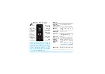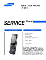
GSM TELEPHONE
GT-C3750
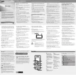
1. Safety Precautions
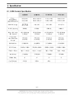
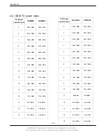
2. Specification
3. Product Function
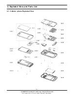
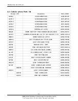
4. Exploded View and Parts list
5. MAIN Electrical Parts List
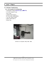
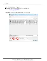
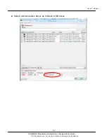
6. Level 1 Repair
7. Level 2 Repair
8. Level 3 Repair
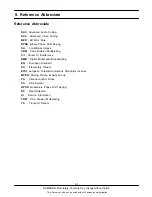
9. Reference data
Notice :
All functionality, features, specifications and other
product information provided in this document inclu
ding, but not limited to, the benefits, design, pricing,
components, performance, availability, and capabiliti
-
es of the product are subject to change without
notice or obligation. Samsung reserves the right to
make changes to this document and the product
described herein, at anytime, without obligation on
Samsung to provide notification of such change.
GSM TELEPHONE
CONTENTS
Summary of Contents for GT-C3750
Page 68: ...www s manuals com ...