background image

SAMSUNG Proprietary-Contents may change without notice

Schematic Diagram

12-5

This Document can not be used without Samsung's authorization

External CODEC


Summary of Contents for GT-M3310

Page 1: ...y Precautions 2 Specification 3 Product Function 4 Array course control 5 Exploded View and Parts List 6 Main Electrical Parts List 7 Block Diagrams 8 PCB Diagrams 9 Flow Chart of Troubleshooting 10 Reference data 11 Disassembly and Assembly instructions ...

Page 2: ...orn away Use a thicken twisted wire when you measure level A thicken twisted wire has low resistance therefore error of measurement is few Repair after separate Test Pack and Set because for short danger for example an overcurrent and furious flames of parts etc when you repair board in condition of connecting Test Pack and tuning on Take specially care of soldering because Land of PCB is small an...

Page 3: ...ined your body before you touch semiconductor or parts with semiconductor There are ways that you touch an earthed place or wear static electricity prevention string on wrist Use earthed soldering steel when you connect or disconnect ESD Use soldering removing tool to break static electricity otherwise ESD will be damaged by static electricity Don t unpack until you set up ESD on product Because m...

Page 4: ...28 251 0 124 975 1023 512 885 512 810 Tx Rx spacing 45MHz 45MHz 95MHz 80MHz Mod Bit rate Bit Period 270 833kbps 3 692us 270 833kbps 3 692us 270 833kbps 3 692us 270 833kbps 3 692us Time Slot Period Frame Period 576 9us 4 615ms 576 9us 4 615ms 576 9us 4 615ms 576 9us 4 615ms Modulation 0 3GMSK 0 3GMSK 0 3GMSK 0 3GMSK MS Power 33dBm 5dBm 33dBm 5dBm 30dBm 0dBm 30dBm 0dBm Power Class 4 max 33dBm 4 max ...

Page 5: ... 9 12 4 dBm 10 10 4 dBm 11 8 4 dBm 12 6 4 dBm 13 4 4 dBm 14 2 5 dBm 15 0 5 dBm TX Power control level GSM850 GSM900 5 33 2 dBm 6 31 2 dBm 7 29 2 dBm 8 27 2 dBm 9 25 2 dBm 10 23 2 dBm 11 21 2 dBm 12 19 2 dBm 13 17 2 dBm 14 15 2 dBm 15 13 2 dBm 16 11 3 dBm 17 9 3 dBm 18 7 3 dBm 19 5 3 dBm TX Power control level DCS1800 0 30 3 dBm 1 28 3 dBm 2 26 3 dBm 3 24 3 dBm 4 22 3 dBm 5 20 3 dBm 6 18 3 dBm 7 16...

Page 6: ...ce 3 Product Function 3 1 This Document can not be used without Samsung s authorization Main Function EDGE 3 2 Mega Pixel CMOS Camera GSM 850 900 1800 1900 Music player Bluetooth FM Radio Motion Control G sensor MicroSD Card Support Automatic EQ DNSe 2 0 ...

Page 7: ... may change without notice 4 Array course control 4 1 This Document can not be used without Samsung s authorization 4 1 Software Adjustments Test Jig GH99 36900A RF Test Cable GH39 00985A Adapter GH99 38251A Test Cable GH39 01290A ...

Page 8: ...le Binary file TFS file CSC file 4 2 2 S W Downloader Program Load the binary download program by executing the OneNAND Downloader v1 6 For PNX6517 tfs4 v1 6 3disk CS3 exe 1 Select the connected serial port and the rate of speed 2 Select the check box the mode you want to download if the binary file wanted check only BIN if the tfs file wanted check only TFS if the csc file wanted check only Commo...

Page 9: ...SAMSUNG Proprietary Contents may change without notice Array course control 4 3 This Document can not be used without Samsung s authorization 4 5 Choose the binary tfs csc file then click open button ...

Page 10: ...control 4 4 This Document can not be used without Samsung s authorization 6 After you select the binary tfs csc file you want to download then click START button Then connect a phone with test cable If connection has no problem the downloader will start pre downloading ...

Page 11: ...SAMSUNG Proprietary Contents may change without notice Array course control 4 5 This Document can not be used without Samsung s authorization 7 Finished the pre downloading click confirm 7 button ...

Page 12: ...tice Array course control 4 6 This Document can not be used without Samsung s authorization 9 Finally click DOWNLOAD 8 button It will start main downloading 4 3 Memory Full reset You should take following procedures in order Memory Full reset 2767 3855 ...

Page 13: ...nd Parts List 5 1 This Document can not be used without Samsung s authorization 5 1 Cellular phone Exploded View QFU01 QAR01 QLC01 QPC01 QCR72 QSP01 QCA01 QCR93 QFL01 QKP01 QCR05 QFR01 QMP01 QME01 QMI01 QSH01 QKP02 QME02 QRE01 QBA01 QCR67 QBC00 QVO01 QAN02 QCR05 QRF06 QCK01 ...

Page 14: ...28A QFU01 ASSY CASE UPPER GH98 14197A QKP01 ASSY KEYPAD MAIN JR SER GH98 14957A QKP02 ASSY KEYPAD SUB JR XEN GH98 14131A QLC01 ASSY LCD GT_M3310 2 1 TN QVGA GH96 04096A QME01 DOME SHEET GT_M3310 GH59 07926A QME02 DOME SHEET GT_M3310 SUB GH59 08452A QMI01 MICROPHONE ASSY GT_M3310 GH30 00604A QMP01 A S ASSY GT_M3310 PBA MAIN GH82 04090A QPC01 ASSY ETC GT_M3310 SLIDE FPCB GH59 07927A QSH01 ASSY BRACK...

Page 15: ...5 001082 V400 V401 V402 V403 VARISTOR 2007 000137 R409 R411 R412 R CHIP 2007 000138 R430 R609 R610 R611 R CHIP 2007 000138 R612 R613 R CHIP 2007 000140 R204 R CHIP 2007 000141 R306 R CHIP 2007 000148 R402 R403 R428 R503 R CHIP 2007 000149 R433 R CHIP 2007 000152 R504 R507 R CHIP 2007 000157 R309 R310 R312 R313 R CHIP 2007 000157 R316 R CHIP 2007 000162 R101 R238 R414 R606 R CHIP 2007 000164 R423 R...

Page 16: ...C140 C CERAMIC CHIP 2203 001385 C126 C127 C128 C131 C CERAMIC CHIP 2203 002668 C105 C CERAMIC CHIP 2203 002709 C207 C213 C230 C CERAMIC CHIP 2203 005053 C102 C124 C125 C CERAMIC CHIP 2203 005054 C139 C CERAMIC CHIP 2203 005234 C133 C134 C CERAMIC CHIP 2203 005288 C153 L116 C CERAMIC CHIP 2203 005446 C121 C122 C CERAMIC CHIP 2203 005450 C218 C CERAMIC CHIP 2203 005481 C438 C439 C CERAMIC CHIP 2203 ...

Page 17: ...77 TA400 TA401 C TA CHIP 2404 001508 C452 C453 C TA CHIP 2703 001726 L117 INDUCTOR SMD 2703 002200 L106 INDUCTOR SMD 2703 002201 L112 INDUCTOR SMD 2703 002203 L107 INDUCTOR SMD 2703 002207 L101 INDUCTOR SMD 2703 002267 L108 L110 INDUCTOR SMD 2703 002281 L109 INDUCTOR SMD 2703 002314 L105 INDUCTOR SMD 2703 002320 L500 INDUCTOR SMD 2703 002365 L400 L401 L402 L403 INDUCTOR SMD 2703 002593 L111 INDUCT...

Page 18: ...esign LOC Discription 3711 005954 HDC601 CONNECTOR HEADER 3711 006141 HDC600 CONNECTOR HEADER 3711 006808 BTC500 CONNECTOR HEADER 3722 002871 IF500 JACK PHONE 3722 002898 EAR500 JACK PHONE 4302 001180 BAT300 BATTERY GH71 08426A ANT100 ANT101 NPR CONTACT ANT Please consuit the GSPN website Samsung Portal for the most recent version of the product s part list ...

Page 19: ...SAMSUNG Proprietary Contents may change without notice 7 Block Diagrams 7 1 This Document can not be used without Samsung s authorization 7 1 RF Solution Block Diagram ...

Page 20: ...L1 GSM GPRS EDGE Rx ARM946 Saturn DSP core Multimedia SIM RF Interface RF Block QS1001 RF IC SKY77344 PAM HWXR876 Crystal Intenna BT Block BC6 BT IC BT Antenna Memory NOR 256M NAND 1G UTRAM 256M External I O Interface Micro USB SIM Card Power PCF50615 PMU Ear Phone 3 5 Pi Audio IC AIT502G Key Pad MIC LCD LCD Panel LCD Back Light Unit Speaker Receiver Motor Slide FPCB PCB Audio Amp MAX9879 ...

Page 21: ...SAMSUNG Proprietary Contents may change without notice 8 PCB Diagrams 8 1 This Document can not be used without Samsung s authorization 8 1 Main Top ...

Page 22: ...SAMSUNG Proprietary Contents may change without notice PCB Diagrams 8 2 This Document can not be used without Samsung s authorization 8 2 Main Bottom ...

Page 23: ... the clock generation circuit related to U102 Check for the clock at CLK 26MHz Yes No Check the VDD_GSM_CORE circuit C332 VDD_GSM_CORE_1 2 V 1 3V Yes No Check the related circuit C161 VDD_IO_LOW C160 VDD_IO_HIGH H Yes No Resolder OSC300 Check the Clock at C317 32KHZ Yes No Check the PMU related to VINT C324 VISA 2 6V Yes No END Change the Battery Power On does not work Check the Battery Voltage is...

Page 24: ... VSS NC 4 VSAVE 40 RF1VDD 27 ONKEY 28 MICBIAS 29 _IRQ 3 REFC 30 REFGND 31 VISA 32 VBATSENSE 33 REC1 2 DCD1VDD 20 D4VDD 21 D5VDD 22 D6VDD 23 SDA 24 SCL 25 26 SIMEN VPAD PWREN2 12 VSS 13 CLK32K 14 DCD2VDD 15 DCD2VBAT 16 DCD2LX 17 DCD1LX 18 DCD1VBAT 19 OSCO PCF50615HN 02 N1 PM300 OSCI 1 GPO1 10 11 PWREN1 AVDD_2 6V C315 C329 C326 C309 SIM_VCC_3 0V MES_BATT C311 L300 VBAT VDD_IO_HIGH_2 9V L301 C312 R31...

Page 25: ...HG 38 39 VSS NC 4 VSAVE 40 RF1VDD 27 ONKEY 28 MICBIAS 29 _IRQ 3 REFC 30 REFGND 31 VISA 32 VBATSENSE 33 REC1 2 DCD1VDD 20 D4VDD 21 D5VDD 22 D6VDD 23 SDA 24 SCL 25 26 SIMEN VPAD PWREN2 12 VSS 13 CLK32K 14 DCD2VDD 15 DCD2VBAT 16 DCD2LX 17 DCD1LX 18 DCD1VBAT 19 OSCO PCF50615HN 02 N1 PM300 OSCI 1 GPO1 10 11 PWREN1 AVDD_2 6V C315 C329 C326 C309 SIM_VCC_3 0V MES_BATT C311 L300 VBAT VDD_IO_HIGH_2 9V L301 ...

Page 26: ... 4 9 3 Charging Part Yes Check the circuit related to V_EXT_CHARGE Check the PM300 pin 46 4 2V PM300 pin 34 L Yes No Abnormal charging part Check the PM300 pin 38 4 9V Yes Check the circuit related to AUX_ON signal Check the circuit related to V_EXT_CHARGE Yes No Yes No Yes No END Abnormal charging part Check the circuit related to MES_BATT signal ...

Page 27: ... VSS NC 4 VSAVE 40 RF1VDD 27 ONKEY 28 MICBIAS 29 _IRQ 3 REFC 30 REFGND 31 VISA 32 VBATSENSE 33 REC1 2 DCD1VDD 20 D4VDD 21 D5VDD 22 D6VDD 23 SDA 24 SCL 25 26 SIMEN VPAD PWREN2 12 VSS 13 CLK32K 14 DCD2VDD 15 DCD2VBAT 16 DCD2LX 17 DCD1LX 18 DCD1VBAT 19 OSCO PCF50615HN 02 N1 PM300 OSCI 1 GPO1 10 11 PWREN1 AVDD_2 6V C315 C329 C326 C309 SIM_VCC_3 0V MES_BATT C311 L300 VBAT VDD_IO_HIGH_2 9V L301 C312 R31...

Page 28: ...ow Chart of Troubleshooting 9 6 9 4 Sim Part SIM300 pin 1 4 C322 H Phone can t access SIM Card Check the SIM charge pump Check the SIM Card END No Yes Yes Yes No Check the Clock After Power ON Check whether SIMCLK Signal on pin3 C334 of SIM300 in a few Yes No Replace PBA After SIM card insert SIM300 pin 2 SIM_RST H Yes ...

Page 29: ...is Document can not be used without Samsung s authorization 9 7 13 14 G G 15 16 G 3 3 4 4 5 5 6 6 7 7 8 8 9 9 G SIM300 1 1 10 10 11 11 12 12 2 2 SIM_VCC_3 0V C335 C322 R304 C334 SIMRST SIMCLK SIMIO C322 C334 C335 C410 C421 C423 C450 C621 F604 F607 L409 L503 R304 R403 R409 R608 SIM300 U602 ...

Page 30: ...tion Flow Chart of Troubleshooting 9 8 9 5 Microphone Part Check the connection from MIC C230 2 1V Resolder MIC Check the path around MIC bias circuit END No Yes Yes Yes Yes No No Replace the MIC Microphone does not work Check the MIC Check the circuit from UCP200 to MIC Yes Check the path from Main IC to MIC No ...

Page 31: ...BIAS_2 1V C410 C450 C440 R403 R409 L407 C421 L406 TA400 TA401 R402 C425 C423 C441 R412 C427 C426 C424 MIC_BIAS_2 1V C428 MIC400 SHORT L409 R411 MIC_P MIC_N EARMICP EARMICN EARMIC_P C230 C400 C401 C402 C404 C405 C407 C408 C409 C438 C451 C601 C603 C630 C639 L400 L401 L402 L501 L502 L504 R213 R214 R238 R604 SPK401 TP_AMP_SHDN TP402 TP403 U401 U402 U601 V400 V401 ZD500 ...

Page 32: ...ng s authorization Flow Chart of Troubleshooting 9 10 9 6 Speaker Part Melody Speaker does not work Check the signal at Pin D4 E4 of U401 1 3V Resolder the C407 C408 Yes No Yes END Is Speaker working Change the Speaker No Yes Check the signal at Pin OUTL OUTR of U401 Resolder or replace U401 Yes No ...

Page 33: ...D5 SCL D6 SDA E1 HPR E2 VDD B5 PGNDR B6 PVDDR C1 VSS C2 GND C3 GND C4 GND C5 GND C6 OUTR A3 PVDDL A4 OUTL A5 PGNDR A6 OUTR B1 C1N B2 PXIN B3 PGNDL B4 RXIN U401 1 NC 2 NC A1 C1P A2 OUTL C437 C408 C415 TP_AMP_SHDN C407 VDD_IO_HIGH_2 9V C438 C403 SDA SCL SHDN 3PI_R 3PI_L AMP_L AMP_R EAR1 EAR2 SPKL_P SPKL_N SPKR_N SPKR_P C401 C402 C403 C405 C406 C407 C408 C411 C412 C415 C416 C437 C438 C439 L400 L401 L...

Page 34: ...1 2 1 2 DIGIT603 SHARP 1 2 1 2 DIGIT602 1 2 DIGIT600 CLEAR 1 2 DIGIT606 1 2 1 2 DIGIT604 SEND 1 2 2 DIGIT607 1 KEY_ROW 3 KEY_ROW 4 KEY_COL 0 KEY_COL 1 KEY_COL 2 KEY_ROW 7 KEY_ROW 2 KEY_ROW 1 KEY_ROW 0 KEY_ROW 0 7 KEY_COL 0 2 9 8 Receiver Part When one of the keys is pushed is it displayed on LCD Check the Dome sheet Key Pad END No Yes Yes Check Initial Operation When one of the keys is pushed KBIO...

Page 35: ...hout notice Flow Chart of Troubleshooting This Document can not be used without Samsung s authorization 9 13 Is Receiver working Resolder UCP200 or change PBA END No Yes Yes Receiver does not work No Replace the Receiver Yes Is Receiver working ...

Page 36: ...ocument can not be used without Samsung s authorization Flow Chart of Troubleshooting 9 14 9 9 Back Light for Color Main LCD Is LCD Contrast set on high level in the Menu Set LCD Contrast on high level END No Yes Yes Backlight does not work Replace the LCD Module ...

Page 37: ... of Troubleshooting This Document can not be used without Samsung s authorization 9 15 9 10 Key Back Light Main key LED does not work Yes PM300 pin23 D6VDD C328 H No Check the KEY_LED_TST line Yes END KEY LED R600 LED600 AEOWU VOYY R601 LED601 AEOWU VOYY VDD_KEY_3 3V ...

Page 38: ...heck the tx chain Check not only the RF Device but also the resistor the inductor and the capacitor Continuous RX ON RF Input 190 CH AMP 50dBm NORMAL CONDITION Catch the channel YES NO Check F101 17pin 55dBm PAM100 Check Pin 13 55dBm U103 Check Pin 19 20 60dBm Check antenna contact Resolder C120 PAM100 Resolder or Change THE END NO NO YES YES YES Resolder C121 C122 L106 or Change U102 NO ...

Page 39: ... the tx chain Check the not only RF Device but also resistor inductor and capacitor Continuous RX ON RF Input 60 CH AMP 50dBm Replace PAM101 NORMAL CONDITION Catch the channel YES NO Check F101 17pin 55dBm PAM100 Check Pin 13 55dBm U102 Check Pin 17 18 60dBm Check antenna contact Resolder C120 PAM100 Resolder or Change THE END NO NO YES YES YES Resolder C124 C125 L107 or Change U102 NO ...

Page 40: ... the tx chain Check the not only RF Device but also resistor inductor and capacitor Continuous RX ON RF Input 698 CH AMP 50dBm Replace PAM101 NORMAL CONDITION Catch the channel YES NO Check F101 17pin 55dBm PAM100 Check Pin 15 55dBm U102 Check Pin 15 16 60dBm Check antenna contact Resolder C120 PAM100 Resolder or Change THE END NO NO YES YES YES Resolder C128 C131 L109 or Change U102 NO ...

Page 41: ... the tx chain Check the not only RF Device but also resistor inductor and capacitor Continuous RX ON RF Input 661 CH AMP 50dBm Replace PAM101 NORMAL CONDITION Catch the channel YES NO Check F101 17pin 55dBm PAM100 Check Pin 15 55dBm U102 Check Pin 13 14 60dBm Check antenna contact Resolder C120 PAM100 Resolder or Change THE END NO NO YES YES YES Resolder C133 C134 L110 or Change U102 NO ...

Page 42: ...SAMSUNG Proprietary Contents may change without notice This Document can not be used without Samsung s authorization Flow Chart of Troubleshooting 9 20 ...

Page 43: ...SAMSUNG Proprietary Contents may change without notice Flow Chart of Troubleshooting This Document can not be used without Samsung s authorization 9 21 ...

Page 44: ...n Check the not only RF Device but also resistor inductor and capacitor YES YES YES YES YES NO NO NO NO NO F101 Check Pin 17 30dBm PAM100 Check Pin 5 30dBm F101 Check Pin 17 30dBm PAM100 Check Pin 5 6dBm THE END Change F101 Check the path from U102 to PAM100 Replace PAM100 Check the OSC100 Resolder C120 U102 Check Pin 36 2 65V Tx ON Level 5 battery voltage 3 8V PAM100 Check Pin 5 30dBm YES NO Reso...

Page 45: ...eck the not only RF Device but also resistor inductor and capacitor YES YES YES YES YES NO NO NO NO NO F101 Check Pin 17 30dBm PAM100 Check Pin 4 30dBm F101 Check Pin 17 30dBm PAM100 Check Pin 4 6dBm THE END Change F101 Check the path from U102 to PAM100 Replace PAM100 Check the OSC100 U102 Check Pin 36 2 65V Tx ON Level 0 battery voltage 3 8V PAM100 Check Pin 4 30dBm YES NO Resolder L108 C126 C12...

Page 46: ...SAMSUNG Proprietary Contents may change without notice This Document can not be used without Samsung s authorization Flow Chart of Troubleshooting 9 24 ...

Page 47: ...SAMSUNG Proprietary Contents may change without notice Flow Chart of Troubleshooting This Document can not be used without Samsung s authorization 9 25 ...

Page 48: ...SK Binary Phase Shift Keying CA Conditional Access CDM Code Division Multiplexing C I Carrier to Interference DMB Digital Multimedia Broadcasting EN European Standard ES Elementary Stream ETSI European Telecommunications Standards Institute MPEG Moving Picture Experts Group PN Pseudo random Noise PS Pilot Symbol QPSK Quadrature Phase Shift Keying RS Reed Solomon SI Service Information TDM Time Div...

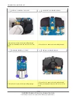
Page 49: ...areful not to make scratch and molding damage 1 Be careful not to make scratch and molding damage 1 Be careful not to make scratch and molding damage 2 When you disassemble connector take care not to tear FPCB 1 Be careful not to make scratch and molding damage 11 1 Disassembly RELEASE SCREWS AT 4 POINT 1 2 3 DISASSEMBLE MAIN PBA DISASSEMBLE MAIN PBA 4 DISASSEMBLE REAR ...

Page 50: ...damage 2 When you disassemble connector take care not to tear FPCB 1 Be careful not to make scratch and molding damage 1 Be careful not to make scratch and molding damage 1 Be careful not to make scratch and molding damage 2 When you disassemble connector take care not to tear FPCB 8 DETACH A SPEAKER MODULE 7 RELEASE SCREWS AT 3 POINT 5 DETACH A CAMERA AT PBA ASS Y UNSOLDER THE SPEAKER MODULE 6 ...

Page 51: ...e scratch and molding damage 1 Be careful not to make scratch and molding damage 1 Be careful not to make scratch and molding damage 2 Take care not to tear FPCB 3 Take care not to tear MOT RCV FPCB 11 RELEASE SCREWS AT 4 POINT DISASSEMBLE LOWER 9 DISASSEMBLE KEYPAD FROM FRONT RELEASE SCREWS AT 6 POINT 10 12 DETACH A MOT RCV FPCB DETACH A SLIDE FPCB DETACH A MOT RCV DETACH A MOT RCV DETACH A MOT R...

Page 52: ...l not to make scratch and molding damage 2 Take care of LCD CRACK 3 Take care of FOG CRACK 1 Be careful not to make scratch and molding damage 2 Take care of LCD CRACK 3 Take care of FOG CRACK 1 Be careful not to make scratch and molding damage 2 Take care of LCD CRACK 3 Take care of FOG CRACK 15 RAISE A LCD TO THE LEFT 13 DISJOINT ONE SET AT A TIME AFTER YOU CONTAIN ASLIDE ASS Y AT CHAMBER RAISE ...

Page 53: ...t 11 5 This Document can not be used without Samsung s authorization 1 Be careful not to make scratch and molding damage 2 Take care of LCD CRACK 3 Take care of FOG CRACK 1 Be careful not to make scratch and molding damage 17 DISASSEMBLE A LCD TO THE LEFT DISASSEMBLE A SUB KEYPAD 18 ...

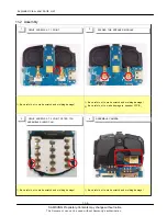
Page 54: ...ke scratch and molding damage 1 Be careful not to make scratch and molding damage 2 Be careful not to make damage to speaker FPCB 1 Be careful not to make scratch and molding damage 1 Be careful not to make scratch and molding damage 11 2 Assembly 1 2 3 4 DRIVE SCREWS AT 1 POINT ASSEMBLE CAMERA DRIVE SCREWS AT 2 POINT AFTER YOU ASSEMBLE SHIELD CAN SOLDER THE SPEAKER MODULE ...

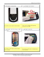
Page 55: ...to make scratch and molding damage 1 Don t touch LCD PCB FOG CRACK generation 2 Take care of FOG CRACK 1 Be careful not to make scratch and molding damage 2 Inside of guideline 1 Be careful not to make scratch and molding damage 2 Inside of guideline 5 ASSEMBLE THE SUB KEYPAD 8 CONNET A SLIDE FPCB 7 ASSEMBLE THE MOT RCV MODULE CONNET A FPCB 6 ASSEMBLE THE LCD MODULE A ...

Page 56: ...eful not to make scratch and molding damage 1 Be careful not to make scratch and molding damage 1 Be careful not to make scratch and molding damage 1 Be careful not to make scratch and molding damage 9 ASSEMBLE LOWER AFTER YOU INSERT SLIDE FPCB BTWEEN LOWER HOLE 10 DRIVE SCREWS AT 4 POINT 12 DRIVE SCREWS AT 6 POINT 11 ATTACH A SCREW COVER ATTACH A SCREW COVER ...

Page 57: ... make scratch and molding damage 1 Be careful not to make scratch and molding damage 2 Take care not to tear Slide FPCB 1 Be careful not to make scratch and molding damage 1 Be careful not to make scratch and molding damage 13 ASSEMBLE A MAIN KEYPAD 14 ASSEMBLE A PBA ASS Y AFTER YOU CONNECT A LCD FPCB 16 1 ASSEMBLE REAR 2 DRIVE SCREWS AT 4 POINT 15 ASSEMBLE A PBA ASS Y ...

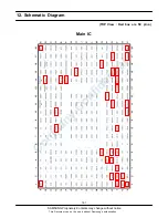
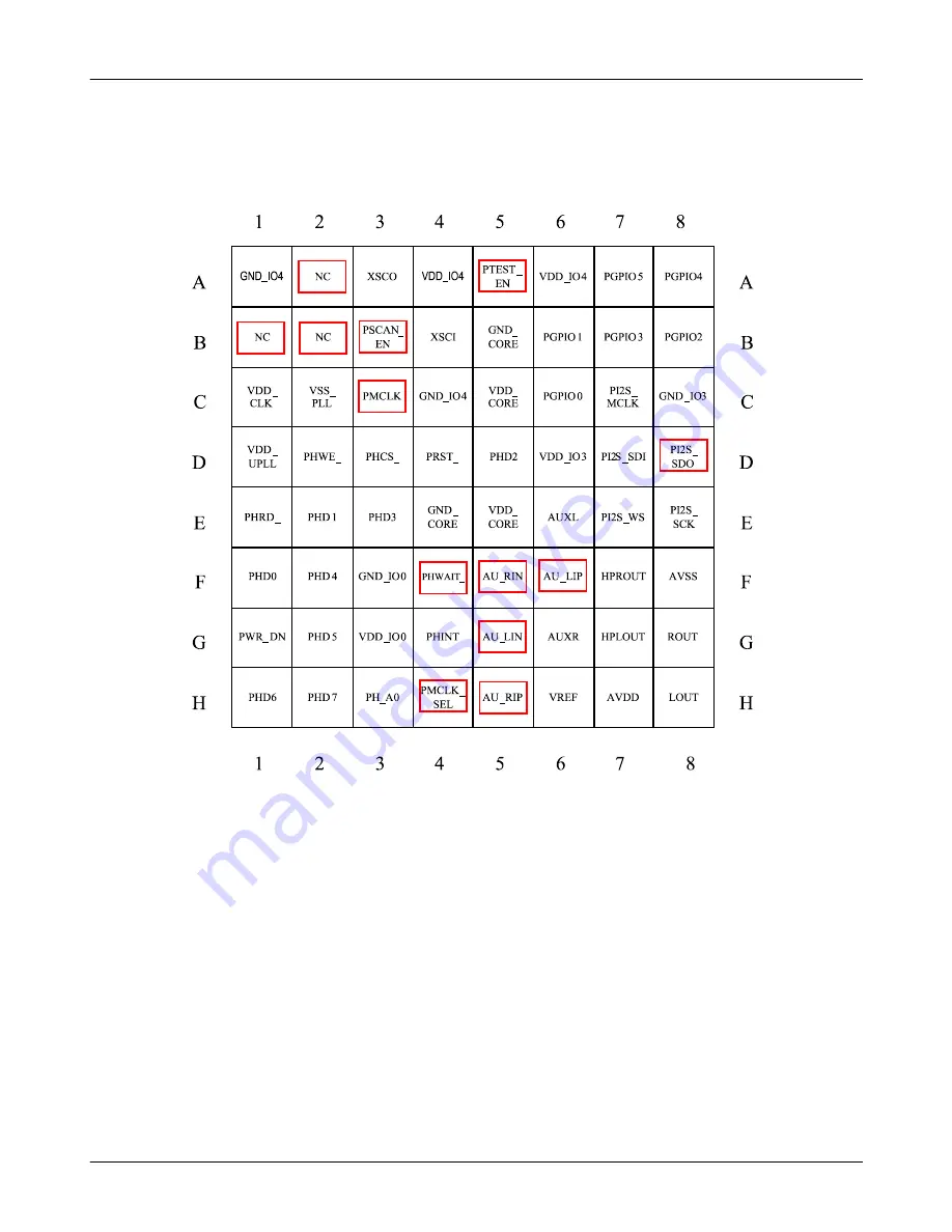
Page 58: ...SAMSUNG Proprietary Contents may change without notice 12 Schematic Diagram 12 1 This Document can not be used without Samsung s authorization TOP View Red box are NC pins Main IC ...

Page 59: ...GND RSTHC VISA SIMOFF VBATSENSE n c REC1 n c REC2 IRQ CHGCUR OSCO USBVIN OSCI VCHG LCVDD VSS CLK32K DCD2VDD DCD2VBAT DCD2LX DCD1LX DCD1VBAT DCD1VDD D4VDD D5VDD D6VDD SDA SCL LCVBA A T D1VDD D3VDD LPVDD D2VDD VBAT IOVDD HCVDD SIMVCC RF2VDD RF1VDD VSAVE 12 11 10 9 8 7 6 5 4 3 2 1 27 28 29 30 31 32 33 34 35 36 37 38 14 15 16 17 18 19 20 21 22 23 24 25 51 50 49 48 47 46 45 44 43 42 41 40 5 2 1 3 3 9 2...

Page 60: ...SAMSUNG Proprietary Contents may change without notice Schematic Diagram 12 3 This Document can not be used without Samsung s authorization AMP ...

Page 61: ...SAMSUNG Proprietary Contents may change without notice Schematic Diagram 12 4 This Document can not be used without Samsung s authorization MEMORY ...

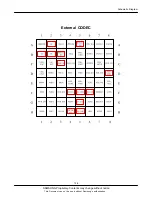
Page 62: ...SAMSUNG Proprietary Contents may change without notice Schematic Diagram 12 5 This Document can not be used without Samsung s authorization External CODEC ...

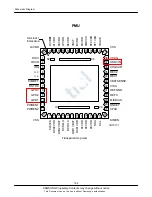
Page 63: ...SAMSUNG Proprietary Contents may change without notice Schematic Diagram 12 6 This Document can not be used without Samsung s authorization PMU ...

Page 64: ...SAMSUNG PROPRIETARY THIS DOCUMENT CONTAINS CONFIDENTIAL PROPRIETARY INFORMATION THAT IS SAMSUNG ELECTRONICS COS PROPERTY DO NOT DISCROSE TO OR DUPLICATE FOR OTHERS EXCEPT AS AUTHORIZED BY SAMSUNG ...

Page 65: ...VCCQO T4 DQ15ROU P9 VCCO R1 VCCQU R10 VSSQ R2 DQ0ROU R3 DQ10ROU R4 DQ11ROU R5 VCCU R6 DNU P10 RDYO P2 DQ8ROU P3 DQ2ROU P4 DQ3ROU P5 DQ4ROU P6 DQ5ROU P7 DQ6ROU P8 DQ1ROU N3 DQ9ROU N4 VSS N5 VCCR N6 _OEU N7 DQ14ROU N8 _OEO N9 _CEO P1 CLKO K3 _AVDO L2 RDYR _WAITU L3 VCCO M10 _AVDRU M2 CLKRU M3 VSS N10 _CER N2 A0ROU E1 A17RU E2 _CSU E4 VCCR E5 A19RU E6 A9ROU E7 A23RU E8 VCCR E9 A1ROU D1 A4ROU D2 A5ROU...

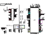
Page 66: ...S 29 _IRQ 3 REFC 30 REFGND 31 VISA 32 VBATSENSE 33 REC1 2 DCD1VDD 20 D4VDD 21 D5VDD 22 D6VDD 23 SDA 24 SCL 25 26 SIMEN VPAD PWREN2 12 VSS 13 CLK32K 14 DCD2VDD 15 DCD2VBAT 16 DCD2LX 17 DCD1LX 18 DCD1VBAT 19 OSCO PCF50615HN 02 N1 PM300 OSCI 1 GPO1 10 11 PWREN1 AVDD_2 6V C315 100PF 50V 6 3V C329 2200nF SIM_VCC_3 0V C326 2200nF 6 3V 1000NF C309 6 3V SIM_VCC_3 0V 470nF MES_BATT 6 3V C311 L300 6 8uH 39P...

Page 67: ...E_ NC B2 PSCAN_EN B3 XSCI B4 GND_CORE B5 PGPIO1 B6 PGPIO3 B7 PGPIO2 B8 VDD_CLK C1 VSS_PLL A2 XSCO A3 VDD_IO4_1 A4 PTEST_EN A5 VDD_IO4_0 A6 PGPIO5 A7 PGPIO4 A8 NC B1 AIT502G U400 NC 1 NC 2 GND_IO4_1 A1 NC L400 18nH INV_EN 2K R412 U403 TC7S04FU TE85L GND 3 IN 2 1 NC OUT 4 5 VCC 100NF 10V C427 C451 1000nF V402 VC040205X150R 16V 22NF C408 SGHP960 MIC SPK400 50V 10PF C415 TP_AMP_SHDN 22NF C407 100K 16V...

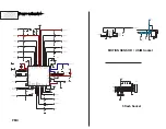
Page 68: ...T NC 5 6 NC NC 7 20K R507 VDD_IO_HIGH_2 9V KQ03SB1 3R BTC500 1 1 2 2 3 3 4 NC L501 BLM15BA330SN1 1005 1005 BLM15AG102SN1D L503 3 4 5 6 C502 100PF PESD5V0U5BV ZD500 1 2 1005 100nH L500 L504 1005 BLM15AG102SN1D 2 GND I O_1 1 I O_2 3 I O_3 4 I O_4 6 5 VCC NC C504 100NF F500 IP4221CZ6 S CON A 2 3 CON B CON C 4 5 CON D 6 SW 25V IJAN4 14 EAR500 33PF 50V R503 10K C501 R523 R524 1M NC 1005 BLM15BA330SN1 L...

Page 69: ...601 14 5805 024 000 829 1 1 10 10 11 GND 9 10 GND IN1 1 2 IN2 3 IN3 4 IN4 OUT1 5 6 OUT2 F601 AMLV 14S 03Q 022 200F VDDA_CAM_2 8V 1 2 DIGIT602 1 2 DIGIT600 CLEAR 1 2 OUT 2 1 VDD U601 HED59XXU12 GND 4 5 GND 3 NC VDDA_CAM_2 8V OUT4 C621 1000NF 6 3V GND IN1 1 2 IN2 IN3 3 4 IN4 OUT1 5 6 OUT2 OUT3 7 8 F602 AMLV 14S 03Q 022 200F GND 9 10 VBAT R601 33 END 1 2 DIGIT606 1 2 1 2 DIGIT604 VDD_CAM_IO_1 8V LED6...

Page 70: ...ngportal com Europe europe samsungportal com China china samsungportal com Asia asia samsungportal com Mideast Africa mea samsungportal com This Service Manual is a property of Samsung Electronics Co Ltd Any unauthorized use of Manual can be punished under applicable International and or domestic law Samsung Electronics Co Ltd 2009 10 Rev 1 0 ⓒ ...

Reviews: