

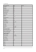


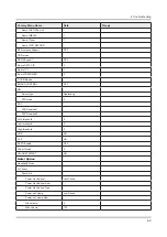

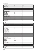


Factory Menu Name
Data
Range
OPTION_HDMI
DVB CI
CAL Data Backup_Copy
…
CAL Data Restore_Copy
…
Expert
ATV IF AGC SPEED
0
Reset
Auto Power
MEMORY
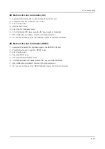
ADC/WB
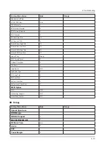
Factory Menu Name
Data
Range
ADC
AV Calibration
Success
Comp Calibraion
Success
PC Calibration
Success
HDMI Calibration
Success
ADC Result
1st_Y_GH
0
1st_Y_GL
0
1st_Cb_BH
0
1st_Cb_BL
0
1st_Cr_RH
0
1st_Cr_RL
0
2nd_R_L
134
2nd_G_L
134
2nd_B_L
134
2nd_R_H
49
2nd_G_H
49
2nd_B_H
49
White Balance
R-Offset
128
G-Offset
128
B-Offset
128
R-Gain
124
G-Gain
128
B-Gain
149
WB_W2_R_Offset
128
4-15
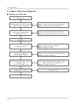
4. Troubleshooting


