background image

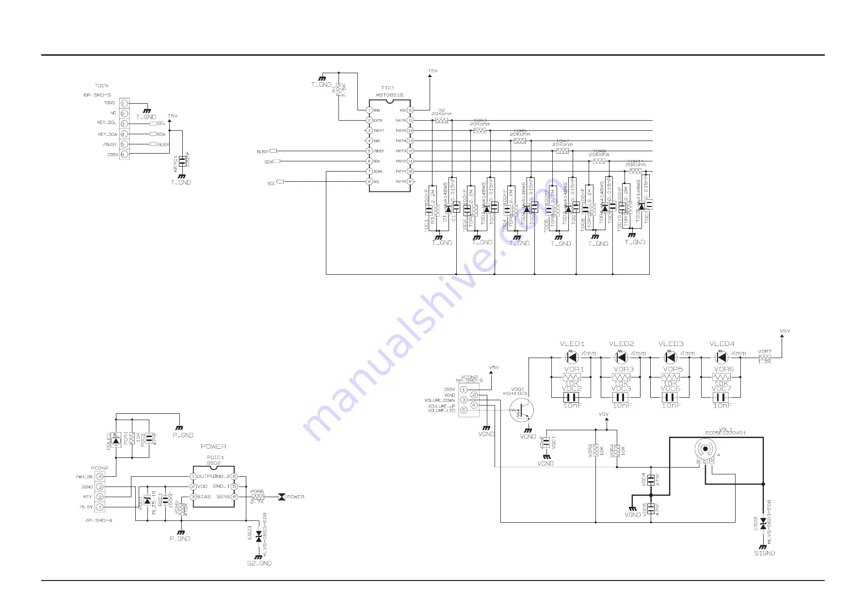
7-4

Samsung Electronics

Schematic Diagram

This Document can not be used without Samsung’s authorization.

7-3  KEY

Summary of Contents for HT-BD1255

Page 1: ...n CONTENTS 1 Precaution 2 Product Specification 3 Disassembly Reassembly 4 Troubleshooting 5 Exploded View Part List 6 PCB Diagram 7 Schematic Diagram 5 1CH Blu ray Home Theater System Model Name HT B...

Page 2: ...domestic law GSPN Global Service Partner Network Area Web Site North America service samsungportal com Latin America latin samsungportal com CIS cis samsungportal com Europe europe samsungportal com...

Page 3: ...Specifications Analysis 2 8 2 4 Accessories 2 10 3 Disassembly Reassembly 3 1 Overall Disassembly Reassembly 3 1 3 2 DECK Disassembly Reassembly 3 4 4 Troubleshooting 4 1 Checkpoints by Error Mode 4...

Page 4: ...Block Diagram 7 2 7 2 FRONT 7 3 7 3 KEY 7 4 7 4 AMP 7 5 7 5 AUDIO VIDEO COMPONENT COMPOSITE 7 6 7 6 HDMI CEC TX SIL9134 7 7 7 7 Boot Strap Option 7 8 7 8 EBI ADDR EBI DATA 7 9 7 9 CLOCK BBS 7 10 7 10...

Page 5: ...Current for Appliances and Underwriters Laboratories UL Publication UL1410 59 7 With the unit completely reassembled plug the AC line cord directly into a 120V AC outlet With the unit s AC switch fir...

Page 6: ...AC power cord for damage Make sure that no wires or components touch thermally hot parts 9 Product Safety Notice Some electrical and mechanical parts have special safety related characteristics which...

Page 7: ...been damaged 5 Check the insulation between the blades of the AC plug and accessible conductive parts examples metal panels input terminals and earphone jacks 6 Insulation Checking Procedure Disconnec...

Page 8: ...umulation of electrostatic charge 4 Do not use freon propelled chemicals These can generate electrical charges that damage ESDs 5 Use only a grounded tip soldering iron when soldering or unsoldering E...

Page 9: ...ng from the beginning of the Mass Production Wireless Network Bundle Wireless LAN adapter not included for HT BD1250 MP3 JPG 2 USB port Not only on rear but also on front I POD Docking Only USA Variou...

Page 10: ...mum Play Time 74 min CD 8 cm COMPACT DISC Reading Speed 4 8 5 6 m sec Maximum Play Time 20 min VIDEO OUTPUT Composite Video 1 channel 1 0 Vp p 75 load Blu ray Disc 576i 480i DVD 576i 480i Component Vi...

Page 11: ...300 x 59 x 50 mm Subwoofer 201 x 403 x 410 mm Weights Front Surround 0 70 Kg Centre 0 33 Kg Subwoofer 5 39 Kg HT BD1252 Speaker Specification SPEAKER Speaker system 5 1ch Speaker System Front Surroun...

Page 12: ...3 Frequency range 140Hz 50KHz 140Hz 20KHz 140Hz 20KHz 40Hz 160Hz Output sound pressure level 87dB W M 87dB W M 87dB W M 88dB W M Rated input 165W 165W 170W 170W Maximum input 330W 330W 340W 340W Dime...

Page 13: ...ayer Disc 135 min CD 12 cm COMPACT DISC Reading Speed 4 8 5 6 m sec Maximum Play Time 74 min CD 8 cm COMPACT DISC Reading Speed 4 8 5 6 m sec Maximum Play Time 20 min VIDEO OUTPUT Composite Video 1 ch...

Page 14: ...m 2 1ch Speaker System Front Subwoofer Impedance 3 3 Frequency range 140Hz 50KHz 40Hz 160Hz Output sound pressure level 87dB W M 90dB W M Rated input 165W 170W Maximum input 330W 340W Dimensions W x H...

Page 15: ...080P 24F 1080P 24F 480i 1080i 480i Only when source is 1080P 24F 1080i 1080i 1080i 1080i 480i 720P 720P 720P 720P 480i 480P 480P 480P 480P 480i 480i 480P 480i 480i 480i DVD playback Output Setup HDMI...

Page 16: ...ot support 1 0 Update Method CD Network USB CD Network Required time for update 3 4min 10 12 min Remote long long HDMI HDMI 1 3 1 3 1080p 24frame CEC Anynet Deep Color X 8bit X 8bit xvYCC X HD Audio T...

Page 17: ...t 480i 480p resolution with Blu ray Disc HT BD2 can also output 480i 480p resolution with Blu ray Disc Audio DD Plus decoding Dolby TrueHD decoding dts HD HRA decoding dts HD Master Audio essential dt...

Page 18: ...2 4 1 Supplied Accessories Accessories Item Item code Remark Remote Control Battery AH59 02144K 4301 000116 Samsung Service Center HDMI Cable AH39 00923A Audio Cable AH39 40001V FM Antenna AH42 00021A...

Page 19: ...ming any work as the IC chips on the PCB are vulnerable to static electricity Assemble in the reverse order of disassembly No Part Name Description Description Photo 1 DECO SIDE 1 Unfasten 2 screws on...

Page 20: ...FRONT 1 Disconnect wire 2 Loosen hooks from CABINET BOTTOM 3 Remove CABINET FRONT from CABINET BOTTOM 4 BRACKET TOP 1 Unfasten 8 screws on the BRACKET TOP BH B M3 L10 ZPC BLK 2 Remove BRACKET TOP fro...

Page 21: ...LK 3 Remove MAIN PCB from CABINET BOTTOM 7 AMP PCB 1 Unfasten 2 screws on the AMP PCB BH B M3 L10 ZPC BLK 2 Unfasten 1 screw on the Rear BH B M3 L10 ZPC BLK 3 Remove AMP PCB from CABINET BOTTOM 8 SMPS...

Page 22: ...ng Electronics Disassembly Reassembly 3 2 DECK Disassembly Reassembly No Part Name Description 1 Ass y Cover 1 Remove 4 Screws 1 2 Lift up the Ass y Cover 2 in direction of arrow 1 4 SCREWS 2X7 W 2 AS...

Page 23: ...ar 2 in the direction arrow Open 2 When the Tray Disc 3 Comes out a little pull it in the direction arrow A by hand 3 Pull the Tray Disc 3 to disassemble while simultaneously pushing 2 Stoppers 4 left...

Page 24: ...y Reassembly No Part Name Description 3 Ass y P U Deck 1 Remove FFC Cable 1 2 3 2 Remove 4 Screws 4 from the Ass y P U Deck 5 and lift it up 2 FFC CABLE BOTTOM VIEW TOP VIEW 1 FFC CABLE 4 4 SCREWS 2 6...

Page 25: ...Ass y Hinge PU 2 and lift it up 2 Pull Bracket Shaft PU 3 in the Direction of Arrow A and Remove Bracket Shaft PU 3 3 Lift Up Shaft P U 4 and Remove the Ass y Pick Up 5 BOTTOM VIEW TOP VIEW 1 1 SCREW...

Page 26: ...P U 2 3 into the Ass y pick up 1 2 Assemble Bracket Shaft PU 4 3 Insert the Ass y Hinge PU 6 Assemble 1 Screw 5 2 SHAFT P U 1 ASS Y PICK UP 3 SHAFT P U ASS Y PICK UP SHAFT P U 1 ASS Y PICK UP 4 BRACKE...

Page 27: ...Samsung Electronics 4 1 Troubleshooting 4 Troubleshooting 4 1 Checkpoints by Error Mode 4 2 4 2 Initialization Upgrade Methods 4 34 4 3 Buyer Region Code Setting Method 4 38...

Page 28: ...v TIME DIV 500ms div 4 1 1 NO POWER Change FL1 Test SMPS PCB No No Change BDL1 Test SMPS PCB No Change IC2 Test SMPS PCB Yes Yes Yes BDL1 TPS10P05G is normal FL1 250V 10A is normal IC2 ICE3B0365J is n...

Page 29: ...Electronics 4 3 Troubleshooting 4 1 2 AMP NO POWER Change IC1 Test SMPS PCB No No Change PCA3 Test SMPS PCB Yes Yes PCA1 2 PC817 is normal IC1 MR4040 is normal AMP No Power Stand by LED ON Change the...

Page 30: ...Change AMP PCB Yes Yes Check AL01 06 of AMP PCB Output Check Check CON1 pin 17 21 of AMP PCB I2S DATA CLK must be inputed There is no audio sound from speaker Check the signal from jack and if not cha...

Page 31: ...Samsung Electronics 4 5 Troubleshooting AMP page 7 5 C O N 1 AMP PCB Top page 6 9 Fig 4 1 1 1...

Page 32: ...4 6 Samsung Electronics Troubleshooting AMP page 7 5 Fig 4 2 1 2 2 2 2 2 2...

Page 33: ...Samsung Electronics 4 7 Troubleshooting AIC2 AIC11 AIC1 AIC4 AIC3 UPIC1 AIC6 AIC5 AMP PCB Top page 6 9 Fig 4 2 2 2...

Page 34: ...NPUT CHECK UPIC1 PS9830B Pin 48 49 51 52 54 55 61 62 67 68 Check PWM OUTPUT CHECK UPIC1 PS9830B POWER 3 3V Pin 4 10 22 29 39 47 56 65 72 84 87 94 Check Replace UPIC1 Check UPIC1 Power pin pattern AIC7...

Page 35: ...s 4 9 Troubleshooting A AIC1 2 3 4 5 6 IRS2092S Pin 11 14 Check No AIC1 2 3 4 5 6 IRS2092S POWER 5V 5V Pin 1 6 Check Yes Replace AIC1 2 3 4 5 6 SOUND OUTPUT OK No Refer to wave pattern image of Fig 4...

Page 36: ...4 10 Samsung Electronics Troubleshooting AMP page 7 5 UPIC1 AMP PCB Top page 6 9 Fig 4 3 1 1 1...

Page 37: ...Samsung Electronics 4 11 Troubleshooting AMP page 7 5 Fig 4 4 1 2 2 2...

Page 38: ...4 12 Samsung Electronics Troubleshooting A I C 7 A I C 8 A I C 9 AMP PCB Bottom page 6 11 Fig 4 4 2 2 2...

Page 39: ...Samsung Electronics 4 13 Troubleshooting AMP page 7 5 Fig 4 5 1 3 3 3 3 3 3...

Page 40: ...4 14 Samsung Electronics Troubleshooting AIC2 AIC11 AIC1 AIC4 AIC3 UPIC1 AIC6 AIC5 AMP PCB Top page 6 9 Fig 4 5 2 3 3...

Page 41: ...DISC LOADING ERROR Check the Power No No Reinsert cables again Yes PICKUP cable and Motor cable inserted correctly Check the FEU1 IC23 8V 5V PiC1 3 3V Disc Ioading error Yes Change the DECK No Change...

Page 42: ...No Re insert FFC cable correctly No Check REYE or change the FRONT PCB Yes Yes Yes Is the FFC cable between Front panel Main OK Remote Battery OK REYE Pin 1 Signal OK Remote control does not work Chan...

Page 43: ...Samsung Electronics 4 17 Troubleshooting FRONT page 7 3 Remote Eye Data TCON1 FRONT PCB Top page 6 3 Fig 4 6 1 1 1...

Page 44: ...sung Electronics Troubleshooting 4 1 7 NO PICTURE Logo screen is OK Yes Yes BD DVD Playback is OK No No No Picture Change the MAIN PCB HDMI No NO LOGO HDMI No Component Yes NO LOGO COMPONENT Yes NO LO...

Page 45: ...connection Yes Yes Yes Clock Data and Sync from Pin 56 94 from IC18 Video selection accords with cable connection and TV mode Pin 51 of IC18 is High 2V 5V No Logo HDMI HDMI Cable Error No Check IC18...

Page 46: ...4 20 Samsung Electronics Troubleshooting HDMI CEC TX SIL9134 page 7 7 Digital Video Signal IC18 C E I C 1 MAIN PCB Top page 6 13 Fig 4 7 1 1 1...

Page 47: ...Samsung Electronics 4 21 Troubleshooting CLOCK BBS page 7 10 54MHz Crystal IC1 C E I C 1 MAIN PCB Top page 6 13 Fig 4 8 2 2 2...

Page 48: ...4 22 Samsung Electronics Troubleshooting HDMI CEC TX SIL9134 page 7 7 HDMI OUTPUT DATA IC18 C E I C 1 MAIN PCB Top page 6 13 Fig 4 9 3 3 3...

Page 49: ...3 VR14 soldering error No Check VIC1 soldering of peripheral devices Yes Yes Yes Video output from VCN1 VR12 VR13 VR14 Video selection accords with cable connection and TV mode Video output from VIC1...

Page 50: ...Samsung Electronics Troubleshooting AUDIO VIDEO COMPONENT COMPOSITE page 7 6 IC18 C E I C 1 C O N 1 8 MAIN PCB Top page 6 13 VR12 Y Signal VR13 Pb Signal VR14 Pr Signal Fig 4 10 1 1 1 VR12 VR13 VR14...

Page 51: ...Samsung Electronics 4 25 Troubleshooting AUDIO VIDEO COMPONENT COMPOSITE page 7 6 VIC1 AIC3 MAIN PCB Bottom page 6 10 VC6 Y Signal VC1 Pb Signal VC4 Pr Signal Fig 4 11 2 2 2 2 2 VC6 VC1 VC4...

Page 52: ...o VCN1 VR16 soldering error No Check VIC1 soldering of peripheral devices Yes Yes Yes Video output from VCN1 VR16 Video selection accords with cable connection and TV mode Video output from VIC1 VC3 R...

Page 53: ...Samsung Electronics 4 27 Troubleshooting AUDIO VIDEO COMPONENT COMPOSITE page 7 6 8 DIC1 PIC6 C O N 1 8 MAIN PCB Top page 6 13 Composit Output CVBS Color Bar VR16 Fig 4 12 1 VR16 1 1...

Page 54: ...4 28 Samsung Electronics Troubleshooting AUDIO VIDEO COMPONENT COMPOSITE page 7 6 VIC1 AIC3 MAIN PCB Top page 6 13 Composit CVBS Color Bar VC3 Fig 4 13 2 VC3 2 2...

Page 55: ...eck No Check the clock at X TAL1 25MHz Yes Check U100 s phreperial part like soldering etc Yes Change the MAIN PCB No Q3 Emitter Voltage check Q2 DVD Q1 CD 4V 6 5 Yes Change the DECK No RFIP Check Sig...

Page 56: ...4 30 Samsung Electronics Troubleshooting BCM7620 F E page 7 20 F E I C 1 3 CON15 C O N 1 6 MAIN PCB Top page 6 13 Fig 4 14 1 1...

Page 57: ...Samsung Electronics 4 31 Troubleshooting BCM7620 F E page 7 20 DSIC14 DSCN1 CON17 MAIN PCB Top page 6 13 DBGN1 CON15 MAIN PCB Bottom page 6 16 Fig 4 15 2 2 2 2 2 2...

Page 58: ...4 32 Samsung Electronics Troubleshooting BCM7620 F E page 7 20 FEIC13 CON15 MAIN PCB Bottom page 6 16 Fig 4 16 3 3...

Page 59: ...nd reset up setting of Network Yes OK Check Network connection Test in the setup menu Cable connection between Set LAN ok Network Error Change the MAIN PCB The connection between LAN and SET is direct...

Page 60: ...Then you will see below screen Method 2 Press MENU on the remote controller Setup System Setup System Information Description for the meaning LDR Loader F W Updatable Front Front Micom F W Not Updatab...

Page 61: ...ray will be opened 3 Press Yes If the update CD you inserted is a later one than Current Version 4 Get rid of update CD from the Disc Tray 5 Wait about 2 3 minutes 6 When Finished power automatically...

Page 62: ...4 36 Samsung Electronics Troubleshooting F W Update via Network...

Page 63: ...word 2 Press on the front panel for over 5 seconds while no disc status 3 Then VFD sign COLD START 4 System Micom Cold Start During Stand By just press on the front panel for over 5 seconds Then Red L...

Page 64: ...properly if you don t insert the region code The region code is inserted by the remote control 1 Press the AUX button on the remote control 2 Press the MARKER button on the remote control during 4 5 s...

Page 65: ...220 2 1CH Region Code Remark USA 00 16 Japan 01 17 Korea 02 18 Taiwan 03 19 Philippines 04 20 Mexico 05 21 Latin American 06 22 Europe 07 23 Indonesia 08 24 Australia 09 25 Russia semi_mic 10 26 Only...

Page 66: ...le during Updating program of System Micom if Updating fail is happened it is impossible to turn on the system from stand by status The system will keep the stand by status continuously and the touch...

Page 67: ...1 Exploded View Part List This Document can not be used without Samsung s authorization 5 Exploded View Part List 5 1 Product Exploded View 5 2 5 2 DECK Exploded View 5 4 5 3 Speaker System 5 6 5 4 El...

Page 68: ...List This Document can not be used without Samsung s authorization 5 1 Product Exploded View S N A Service Not Available A4 AD150 T0076 AD330 AD502 AD504 AS260 T0076 AL180 VFILT AC010 AD340 AM020 AA50...

Page 69: ...BD1250 PMMA MILKY MILKY W 1 SA AM020 AH31 00039B MOTOR FAN C151BK10A2430 RDM5015S 0 12A 1 1 SA AS260 AH61 02527A SPRING ETC DOOR HT Z310 STS 304 WPS 0 2 1 SA FL261 3809 002242 FFC CABLE FLAT 30V 80C...

Page 70: ...cs Exploded View Part List This Document can not be used without Samsung s authorization 5 2 DECK Exploded View W901 2 x 7 W SCREW 1 7 x 5 W SCREW 2 6 x 6 W SCREW H400 H401 H301 H501 W900 H301 H200 H3...

Page 71: ...AK96 01024A ASSY TRAVERSE BD P5 1 SA H301 AK61 00736A BRACKET SHAFT PU DP R3 5 SUS T1 0 4 SA H400 AK96 01025A ASSY HINGE PU BD P5 1 SA H401 6002 001086 SCREW TAPPING PH B M1 7 L5 0 ZPC 1 SA H500 AK92...

Page 72: ...AKER PS BD1250 CENTER SPEAKER SYSTEM UHL XXA 1 SA Rear Speaker L AH81 05111B SPEAKER AH81 05111 PS BD1250 CENTER SPEAKER SYSTEM UHL XXA 1 SA Rear Speaker R AH81 05112B SPEAKER PS BD1250 REAR SPEAKER S...

Page 73: ...L SW FOR PS Z520 1 SA AH81 04922A SPEAKER A S PART CABINET SUBWOOFER 1 SA AH81 04971A A S SUBWOOFER UNIT FOR PS WZ520 16 1 SA AH81 05119B LABEL PS BD1250 SUBWOOFER LABEL XXA 1 SNA PCB KEY AH92 03060A...

Page 74: ...STRAIGHT A 1 SA USC1 2203 005249 C CER CHIP 100nF 10 50V X7R TP 160 1 SA USC5 2203 006361 C CER CHIP 10000nF 10 10V X5R TP 2 1 SA USD1 0406 001128 DIODE TVS MLVS 0603 E08 50V 1 SA VCON1 3708 001618 CO...

Page 75: ...1005 1 SA C31 2203 006158 C CER CHIP 100nF 10 16V X7R 1005 1 SA C311 2404 001035 C TA CHIP 10uF 10 25V TP 6032 1 SA C313 2402 001237 C AL SMD 330uF 20 6 3V TP 6 3x7 1 SA C314 2402 001276 C AL SMD 47uF...

Page 76: ...CHIP 0 47nF 5 50V NP0 1608 1 SA DC10 2203 006158 C CER CHIP 100nF 10 16V X7R 1005 1 SA DC11 2203 006361 C CER CHIP 10000nF 10 10V X5R TP 2 1 SA DC12 2203 006361 C CER CHIP 10000nF 10 10V X5R TP 2 1 S...

Page 77: ...ohm 5 1 16W TP 1005 1 SA DPR33 2007 001292 R CHIP 33ohm 5 1 16W TP 1005 1 SA DPR34 2007 001292 R CHIP 33ohm 5 1 16W TP 1005 1 SA DPR35 2007 001292 R CHIP 33ohm 5 1 16W TP 1005 1 SA DPR36 2007 001292 R...

Page 78: ...1005 1 SA FEC102 2203 005249 C CER CHIP 100nF 10 50V X7R TP 160 1 SA FEC103 2203 006048 C CER CHIP 100nF 10 10V X7R 1005 1 SA FEC104 2203 006048 C CER CHIP 100nF 10 10V X7R 1005 1 SA FEC105 2203 0060...

Page 79: ...1292 R CHIP 33ohm 5 1 16W TP 1005 1 SA FER121 2007 000170 R CHIP 1Mohm 5 1 16W TP 1005 1 SA FER18 2007 000157 R CHIP 47Kohm 5 1 16W TP 1005 1 SA FER19 2007 000157 R CHIP 47Kohm 5 1 16W TP 1005 1 SA FE...

Page 80: ...48 C CER CHIP 100nF 10 10V X7R 1005 1 SA HC9 2203 006048 C CER CHIP 100nF 10 10V X7R 1005 1 SA HCN1 3701 001313 CONNECTOR HDMI 19P 2R PLUG ANGLE AU 1 SA HD1 1405 001192 VARISTOR 12Vdc 30A 1 6x0 8x0 55...

Page 81: ...1Gbit 1 SA MEM4 1105 001942 IC DDR2 SDRAM K4T1G164Q DDR2 1Gbit 1 SA MR10 2007 000043 R CHIP 1Kohm 1 1 10W TP 1608 1 SA MR4 2007 000779 R CHIP 33ohm 1 1 10W TP 1608 1 SA MR5 2007 000779 R CHIP 33ohm 1...

Page 82: ...10000nF 10 10V X5R TP 2 1 SA PC51 2203 006361 C CER CHIP 10000nF 10 10V X5R TP 2 1 SA PC52 2203 006361 C CER CHIP 10000nF 10 10V X5R TP 2 1 SA PC55 2203 006361 C CER CHIP 10000nF 10 10V X5R TP 2 1 SA...

Page 83: ...P 1005 1 SA R152 2007 000242 R CHIP 1 5Kohm 5 1 16W TP 1005 1 SA R153 2007 000143 R CHIP 4 7Kohm 5 1 16W TP 1005 1 SA R156 2007 001305 R CHIP 120ohm 5 1 16W TP 1005 1 SA R157 2007 001305 R CHIP 120ohm...

Page 84: ...SA UR16 2007 000171 R CHIP 0ohm 5 1 16W TP 1005 1 SA UR17 2007 000029 R CHIP 0ohm 5 1 8W TP 2012 1 SA UR19 2007 000151 R CHIP 15Kohm 5 1 16W TP 1005 1 SA UR2 2007 000151 R CHIP 15Kohm 5 1 16W TP 1005...

Page 85: ...00nF 10 100V X7R TP 32 1 SA AMC126 2203 000257 C CER CHIP 10nF 10 50V X7R TP 1608 1 SA AMC127 2203 005249 C CER CHIP 100nF 10 50V X7R TP 160 1 SA AMC128 2203 005249 C CER CHIP 100nF 10 50V X7R TP 160...

Page 86: ...ER CHIP 100nF 10 50V X7R TP 160 1 SA AMC41 2402 001049 C AL SMD 10uF 20 16V GP TP 3 3x3 3 1 SA AMC42 2203 006698 C CER CHIP 1000nF 10 25V X7R 1608 1 SA AMC43 2203 006698 C CER CHIP 1000nF 10 25V X7R 1...

Page 87: ...2007 000084 R CHIP 4 7Kohm 5 1 10W TP 1608 1 SA AMR121 2007 000090 R CHIP 10Kohm 5 1 10W TP 1608 1 SA AMR122 2007 000134 R CHIP 33Kohm 5 1 10W TP 1608 1 SA AMR123 2007 000312 R CHIP 10ohm 5 1 4W TP 32...

Page 88: ...m 5 1 10W TP 1608 1 SA AMR228 2007 000097 R CHIP 47Kohm 5 1 10W TP 1608 1 SA AMR229 2007 000087 R CHIP 6 8Kohm 5 1 10W TP 1608 1 SA AMR23 2007 000078 R CHIP 1Kohm 5 1 10W TP 1608 1 SA AMR230 2007 0000...

Page 89: ...MR87 2007 000265 R CHIP 1 8Kohm 1 1 10W TP 1608 1 SA AMR88 2007 000075 R CHIP 220ohm 5 1 10W TP 1608 1 SA AMR89 2007 001179 R CHIP 8 2Kohm 5 1 10W TP 1608 1 SA AMR9 2007 000122 R CHIP 1 2Kohm 5 1 10W...

Page 90: ...0V C0G TP 16 1 SA UAC36 2203 000646 C CER CHIP 0 024NF 5 50V C0G TP 16 1 SA UAC37 2203 005249 C CER CHIP 100nF 10 50V X7R TP 160 1 SA UAC38 2203 006361 C CER CHIP 10000nF 10 10V X5R TP 2 1 SA UAC39 22...

Page 91: ...1 Wiring Diagram 6 2 6 2 FRONT PCB Top 6 3 6 3 FRONT PCB Bottom 6 5 6 4 KEY PCB Top 6 6 6 5 KEY PCB Bottom 6 8 6 6 AMP PCB Top 6 9 6 7 AMP PCB Bottom 6 11 6 8 MAIN PCB Top 6 13 6 9 MAIN PCB Bottom 6...

Page 92: ...OUT 15 GND 12 BCLKOUT 16 BDSLEEP 13 GND 17 GAINSW 14 GND 18 VREFB 15 AV 3 3V 19 VREFB 16 DS 5V 20 5V 17 EXT_MUTE PWM 21 RFID 18 RESET PWM 22 RFIN 19 SO PWM 23 GG 20 CS PWM 24 HH 21 SCK PWM 25 EE 22 SI...

Page 93: ...Samsung Electronics 6 3 PCB Diagram 6 2 FRONT PCB Top 1 2 TP4 I J K I J K VCON1 BCON1 MMIC1 UIC2 UCON1 TCON1 IC1 PCON1 FCON1...

Page 94: ...TA 14 POWER_LED 15 16 MIC_CLK 17 POWER_TOUCH_1KEY 18 19 BTRST 20 BUZZER 21 GND 22 VOL_DOWN 23 VOL_UP 24 TC_SDA 25 TOUCH_CLK 26 TOUCHRST 27 TOUCH_INT 28 GND 2 IC1 VFD Control Signal Pin No Signal Pin N...

Page 95: ...Samsung Electronics 6 5 PCB Diagram 6 3 FRONT PCB Bottom I J K I J K VCON1 BCON1 MMIC1 UIC2 UCON1 TCON1 PCON1 FCON1 IC1...

Page 96: ...6 6 Samsung Electronics PCB Diagram 6 4 KEY PCB Top 1 2 TIC1 PCON2 VCON2 TCON...

Page 97: ...ectronics 6 7 PCB Diagram 6 4 1 Pin Connection 2 PCON2 FRONT POWER KEY Pin No Signal 1 POWER_ON 2 DGND 3 KEY 4 5 6V 1 TCON FRONT FUNCTION KEY Pin No Signal 1 5V 2 KEY_INT 3 KEY_SDA 4 KEY_SCL 5 KEY_RES...

Page 98: ...6 8 Samsung Electronics PCB Diagram 6 5 KEY PCB Bottom...

Page 99: ...Samsung Electronics 6 9 PCB Diagram 6 6 AMP PCB Top 1 2 TP1 TP3 AIC2 AIC11 AIC1 AIC4 AIC3 UPIC1 AIC6 AIC5 CON1 J3...

Page 100: ...35V 6 35V 7 35V 8 GND 9 GND 10 35V 11 35V 12 35V 1 CON1 MAIN AMP DATA LINE Pin No Signal 1 2 3 AVGND 4 MIC_PDN 5 SD POWER 6 RESET POWER 7 8 AUOUT3 9 AUOUT2 10 AUOUT1 11 LRCKOUT 12 BCLKOUT 13 GND 14 GN...

Page 101: ...Samsung Electronics 6 11 PCB Diagram 6 7 AMP PCB Bottom TP2 CON1 J3 AIC7 AIC8 AIC9...

Page 102: ...6 12 Samsung Electronics PCB Diagram 6 7 1 Test Point Wave Form TP2...

Page 103: ...s 6 13 PCB Diagram 6 8 MAIN PCB Top 1 3 2 4 5 TP6 TP5 TP7 TP8 TP9 TP10 IC18 DSIC1 DSIC14 DIC1 PIC6 IPIC2 PIC5 CEIC1 U1 MEM2 MEM1 MEM4 MEM3 FEIC13 DJ3 MUCN2 IPCN1 PCN1 SCN2 CON12 DSCN1 CON17 CON15 CON1...

Page 104: ...N12 MAIN Loader Loader Power Line Pin No Signal 1 SW3 2 LDO 3 LDO 4 CLOSE 5 OPEN 6 GND 7 W 8 V 9 U 10 GND 11 H 12 HU 13 HU 14 HW 15 HW 16 H 17 HV 18 HV 19 SLD2 20 SLD2 21 SLD1 22 SLD1 4 PCN1 MAIN SMPS...

Page 105: ...Samsung Electronics 6 15 PCB Diagram 6 8 2 Test Point Wave Form TP6 TP5 TP7 TP8 TP9 TP10...

Page 106: ...6 16 Samsung Electronics PCB Diagram 6 9 MAIN PCB Bottom TP7 TP8 TP9 TP10 VIC1 DSIC1 AIC3 DSIC5 MUIC1 FEIC13 DJ3 MUCN2 PCN1 DBGN1 CON15 USCON1 J2...

Page 107: ...Samsung Electronics 6 17 PCB Diagram 6 9 1 Test Point Wave Form TP7 TP8 TP9 TP10...

Page 108: ...6 18 Samsung Electronics PCB Diagram 6 10 SMPS PCB Top CN3 CN2...

Page 109: ...Samsung Electronics 6 19 PCB Diagram 6 11 SMPS PCB Bottom CN3 CN2...

Page 110: ...6 20 Samsung Electronics MEMO...

Page 111: ...OSITE 7 6 7 6 HDMI CEC TX SIL9134 7 7 7 7 Boot Strap Option 7 8 7 8 EBI ADDR EBI DATA 7 9 7 9 CLOCK BBS 7 10 7 10 BCM7440 POWER 7 11 7 11 DDR2 BANK0 BANK1 7 12 7 12 SYSTEM MICOM TUNER SRC WIRELESS 7 1...

Page 112: ...T BD1250 function IC For HDMI 1080P BCM7440P transfer the digital video signal with 24bit to HDMI TX chip SIL9134 BCM7440P doesn t need external up scaling IC because it has a own internal scalar Abou...

Page 113: ...Samsung Electronics 7 3 Schematic Diagram This Document can not be used without Samsung s authorization 7 2 FRONT TP4 TP4...

Page 114: ...7 4 Samsung Electronics Schematic Diagram This Document can not be used without Samsung s authorization 7 3 KEY...

Page 115: ...Samsung Electronics 7 5 Schematic Diagram This Document can not be used without Samsung s authorization 7 4 AMP TP1 TP2 TP2 TP2 TP3 TP3 TP3 TP3 TP3 TP3 TP1 TP3 TP2...

Page 116: ...Samsung Electronics Schematic Diagram This Document can not be used without Samsung s authorization 7 5 AUDIO VIDEO COMPONENT COMPOSITE TP10 TP7 TP8 TP9 TP10 TP8 TP9 TP7 TP7 TP8 TP9 TP10 POWER AUDIO V...

Page 117: ...Samsung Electronics 7 7 Schematic Diagram This Document can not be used without Samsung s authorization 7 6 HDMI CEC TX SIL9134 TP5 TP5 TP5 POWER AUDIO VIDEO...

Page 118: ...7 8 Samsung Electronics Schematic Diagram This Document can not be used without Samsung s authorization 7 7 Boot Strap Option POWER...

Page 119: ...Samsung Electronics 7 9 Schematic Diagram This Document can not be used without Samsung s authorization 7 8 EBI ADDR EBI DATA POWER...

Page 120: ...7 10 Samsung Electronics Schematic Diagram This Document can not be used without Samsung s authorization 7 9 CLOCK BBS TP6 TP6 POWER...

Page 121: ...Samsung Electronics 7 11 Schematic Diagram This Document can not be used without Samsung s authorization 7 10 BCM7440 POWER POWER...

Page 122: ...7 12 Samsung Electronics Schematic Diagram This Document can not be used without Samsung s authorization 7 11 DDR2 BANK0 BANK1 POWER...

Page 123: ...Samsung Electronics 7 13 Schematic Diagram This Document can not be used without Samsung s authorization 7 12 SYSTEM MICOM TUNER SRC WIRELESS POWER AUDIO...

Page 124: ...7 14 Samsung Electronics Schematic Diagram This Document can not be used without Samsung s authorization 7 13 EXTERNAL IN AUDIO FLOW POWER AUDIO...

Page 125: ...Samsung Electronics 7 15 Schematic Diagram This Document can not be used without Samsung s authorization 7 14 Ethernet S ATA USB POWER...

Page 126: ...7 16 Samsung Electronics Schematic Diagram This Document can not be used without Samsung s authorization 7 15 GPIO IPOD BT POWER AUDIO VIDEO...

Page 127: ...Samsung Electronics 7 17 Schematic Diagram This Document can not be used without Samsung s authorization 7 16 NAND FlexOneNand POWER...

Page 128: ...7 18 Samsung Electronics Schematic Diagram This Document can not be used without Samsung s authorization 7 17 MAIN POWER POWER...

Page 129: ...Samsung Electronics 7 19 Schematic Diagram This Document can not be used without Samsung s authorization 7 18 DSP SDRAM FLASH POWER AUDIO...

Page 130: ...7 20 Samsung Electronics Schematic Diagram This Document can not be used without Samsung s authorization 7 19 BCM7620 F E POWER...

Page 131: ...ctronics 7 21 Schematic Diagram This Document can not be used without Samsung s authorization 7 20 SMPS 110V ORTP 527 T1 ORTP 527 T2 15uH L62 L71 33uH 3A L61 33uH 5A SOD 123 2 9uH BAR TYPE L52 2 9uH B...

Page 132: ...g Electronics Schematic Diagram This Document can not be used without Samsung s authorization 7 21 SMPS 220V ORTP 527 T1 ORTP 527 T2 15uH L62 L71 33uH 3A L61 33uH 5A SOD 123 2 9uH BAR TYPE L52 2 9uH B...

Reviews: