Samsung Electronics
4-17
Troubleshooting
4-2 Measures to be taken when the Protection Circuit operates
4-2-1 SMPS Protection
The Condition of Power Protection Active.
1. Voltage of SMPS’s +, - PVDD (+30V, -30V) is higher or lower than Standards
Normal Condition Voltage Range: PVDD (+30V, -30V): about +30V, -30V
2. Over-current occurs to FET (Over-output or Output short)
3. FET’s temperature exceed 150°C.
4. No supply voltage on GATE DRIVER.
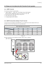
4-2-2 AMP Pre-Inspection relating to Power Protection
If you think, there are problems at the AMP PCB, you can check the pcb without disassemble the set.
(Caution!!: Do not connect the power cord during bellow test!)
Measurement Resistance using Tester
- Approximately
C550
C650
C450
F/R CH
1.8Ω
1.8Ω
1.8Ω
CENTER
1.8Ω
1.8Ω
1.8Ω
SUBWOOFER
1.8ΩΩ
1.8Ω
1.8Ω
<Table 4-1>
If Measured Resistance is very different from above numbers. There is a Problem.
→ AMP PCB Problem
5.1CH SPEAKER OUTPUT
GND
FRONT R
CENTER
FRONT L
REAR R
REAR L
SUBWOOFER
Summary of Contents for HT-C553
Page 8: ...3 4 Samsung Electronics MEMO...
Page 23: ...6 2 Samsung Electronics PCB Diagram 6 2 FRONT PCB Top FCON1 UIC2 KIC2 U1 2 1...
Page 25: ...6 4 Samsung Electronics PCB Diagram 6 3 FRONT PCB Bottom...
Page 26: ...Samsung Electronics 6 5 PCB Diagram 6 4 KEY PCB Top...
Page 27: ...6 6 Samsung Electronics PCB Diagram 6 5 KEY PCB Bottom CN1 IC1 1...
Page 31: ...6 10 Samsung Electronics PCB Diagram TP1 TP2 TP3 TP4 TP5 6 6 2 Test Point Wave Form TP6 TP7...
Page 33: ...6 12 Samsung Electronics PCB Diagram 6 8 SMPS PCB Top CON1...
Page 34: ...Samsung Electronics 6 13 PCB Diagram 6 9 SMPS PCB Bottom CON2 CON3...
Page 35: ...6 14 Samsung Electronics MEMO...
Page 47: ...2 8 Samsung Electronics MEMO...


