background image

DVD RECEIVER AMP

HT-DS700
HT-DS760(T)
HT-DS900
HT-DS1750
HT-DS1870

SERVICE

Manual

DVD RECEIVER AMP SYSTEM

CONTENTS

1. Alignment and Adjustments

2. Exploded Views and Parts List

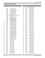
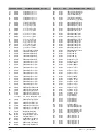
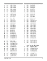
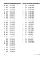
3. Electrical Parts List

4. Block Diagrams

5. Wiring Diagram

6. Schematic Diagrams

7. IC Block Diagrams

8. Troubleshooting

- Confidential -

Summary of Contents for HT-DS700

Page 1: ...1750 HT DS1870 SERVICEManual DVD RECEIVER AMP SYSTEM CONTENTS 1 Alignment and Adjustments 2 Exploded Views and Parts List 3 Electrical Parts List 4 Block Diagrams 5 Wiring Diagram 6 Schematic Diagrams...

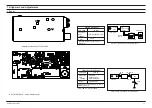
Page 2: ...o that TUNED of FLT is lighted Figure 1 2 Figure1 2 FM Auto Search Level Adjustment Adjust FM S S G level to 28dB Figure1 1 IF CENTER and THD Adjustment SSG FREQ Adjustment point SVR1 98 MHz BEACON SE...

Page 3: ...Samsung Electronics 2 1 2 Exploded Views and Parts List 2 1 Total Exploded View...

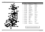
Page 4: ...T SECC 0 8T 1 17 AH64 02585B DECO BOTTOM L ABS BLK 1 18 AH64 02584B DECO BOTTOM R ABS BLK 1 19 AH61 00774A HOLDER PCB ABS GRAY 1 20 AH64 02844A CABINET BOTTOM SECC 0 8T 1 21 AH61 01355A BRACKET TUNER...

Page 5: ...HOLDER BRACKET SECC t0 8 11 AH31 00030B MOTOR DC RF 300E 1D390 12 AH41 00560A PCB SWITCH 43 5 32 5 13 AH66 00219A BELT PULLEY CR 1 2 14 3409 001119 SWITCH DETECTOR JDS2200 15 AH59 01184A DVD DECK ASS...

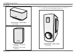
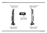
Page 6: ...g Electronics 2 4 2 3 SPEAKER Composite View 2 3 1 HT DS700 CAUTION The NET FRAME or FRONT PANEL ASS Y uses bonding to connect to CABINET ASS Y The extreme care not to damage the SPEAKER during disass...

Page 7: ...Samsung Electronics 2 5 2 3 2 HT DS760T...

Page 8: ...Samsung Electronics 2 6 CAUTION The NET FRAME or FRONT PANEL ASS Y uses bonding to connect to CABINET ASS Y The extreme care not to damage the SPEAKER during disassembly 2 3 3 HT DS900...

Page 9: ...100ohm 5 1 10W TP 1608 PR26 2007 000074 R CHIP 100ohm 5 1 10W TP 1608 PR25 2007 000074 R CHIP 100ohm 5 1 10W TP 1608 PR24 2007 000074 R CHIP 100ohm 5 1 10W TP 1608 PR23 2007 000074 R CHIP 100ohm 5 1 1...

Page 10: ...052 C CER CHIP 0 56nF 10 50V X7R TP 1608 MC27 2203 001052 C CER CHIP 0 56nF 10 50V X7R TP 1608 MC21 2203 001103 C CER CHIP 6 8nF 10 50V X7R TP 1608 RC6 2203 001222 C CER CHIP 0 82NF 10 50V X7R TP 1608...

Page 11: ...3 TR SMALL SIGNAL KSA733 PNP 250mW TO 92 T SQ7R 0501 000341 TR SMALL SIGNAL KSC1623 L NPN 200mW SOT SQ7L 0501 000341 TR SMALL SIGNAL KSC1623 L NPN 200mW SOT SQ3 0501 000637 TR SMALL SIGNAL 2SC1740S NP...

Page 12: ...5128A LQFP 64P 1063MIL FR20 2001 000552 R CARBON 270OHM 5 1 4W AA TP 2 4X6 4MM JW6 2007 000029 R CHIP 0ohm 5 1 8W TP 2012 JW7 2007 000029 R CHIP 0ohm 5 1 8W TP 2012 JW8 2007 000029 R CHIP 0ohm 5 1 8W...

Page 13: ...CHIP 100nF 10 50V X7R TP 1608 UC74 2203 005249 C CER CHIP 100nF 10 50V X7R TP 1608 UC73 2203 005249 C CER CHIP 100nF 10 50V X7R TP 1608 UC72 2203 005249 C CER CHIP 100nF 10 50V X7R TP 1608 UC71 2203...

Page 14: ...000253 R CHIP 1 5ohm 5 1 4W TP 3216 R129 2007 000253 R CHIP 1 5ohm 5 1 4W TP 3216 R6FL 2007 000253 R CHIP 1 5ohm 5 1 4W TP 3216 R6C 2007 000253 R CHIP 1 5ohm 5 1 4W TP 3216 R46 2007 000253 R CHIP 1 5o...

Page 15: ...C CER CHIP 100nF 10 50V X7R TP 1608 C9RL 2203 005249 C CER CHIP 100nF 10 50V X7R TP 1608 C9RR 2203 005249 C CER CHIP 100nF 10 50V X7R TP 1608 C9S 2203 005249 C CER CHIP 100nF 10 50V X7R TP 1608 C7RR...

Page 16: ...Samsung Electronics 4 1 4 Block Diagram 4 1 MAIN Part...

Page 17: ...4 2 Samsung Electronics 4 2 DVD Part...

Page 18: ...Samsung Electronics 5 1 5 Wiring Diagram...

Page 19: ...Samsung Electronics 6 1 This Document can not be used without Samsung s authorization 6 Schematic Diagram 6 1 1 MAIN RCA...

Page 20: ...6 2 Samsung Electronics This Document can not be used without Samsung s authorization 6 1 2 MAIN SCART...

Page 21: ...Samsung Electronics 6 3 This Document can not be used without Samsung s authorization 6 2 FRONT...

Page 22: ...6 4 Samsung Electronics This Document can not be used without Samsung s authorization 6 3 AMP...

Page 23: ...Samsung Electronics 6 5 This Document can not be used without Samsung s authorization 6 4 MICOM FRONT...

Page 24: ...6 6 Samsung Electronics This Document can not be used without Samsung s authorization 6 5 TUNER...

Page 25: ...Samsung Electronics 6 7 This Document can not be used without Samsung s authorization 6 6 DVD PACK...

Page 26: ...Samsung Electronics 7 1 7 IC Block Diagrams 7 1 Main 7 1 1 FAN8082...

Page 27: ...7 2 Samsung Electronics 7 1 2 MAX232...

Page 28: ...Samsung Electronics 7 3 7 1 3 TAS5121...

Page 29: ...7 4 Samsung Electronics 7 1 4 S5G5128A...

Page 30: ...Samsung Electronics 7 5...

Page 31: ...7 6 Samsung Electronics 7 1 6 WM8775 7 1 5 PS9818...

Page 32: ...Samsung Electronics 7 7 7 2 DVD 7 2 1 A29L160 7 2 2 ESMT_M12L128168A...

Page 33: ...7 2 4 S524C20D21_20D41 7 8 Samsung Electronics 7 2 3 74HCT245...

Page 34: ...Samsung Electronics 7 9 7 2 6 STM_74LCX244 7 2 5 STM_74LCX157...

Page 35: ...7 10 Samsung Electronics 8 2 7 STM_74LCX374...

Page 36: ...Samsung Electronics 7 11 7 3 MICOM PORT ASSIGNMENT...

Page 37: ...Samsung Electronics 8 1 8 TroubleShooting 8 1 Main...

Page 38: ...8 2 Samsung Electronics...

Page 39: ...Samsung Electronics 8 3 8 2 DVD SERVO parts...

Page 40: ...8 4 Samsung Electronics...

Page 41: ...Samsung Electronics 8 5...

Page 42: ...8 6 Samsung Electronics...

Page 43: ...Samsung Electronics 8 7...

Page 44: ...8 8 Samsung Electronics...

Page 45: ...Samsung Electronics 8 9...

Page 46: ...8 10 Samsung Electronics 8 3 DVD MPEG Parts...

Page 47: ...Samsung Electronics 8 11...

Reviews: