6.
Schematic Diagram
6. Schematic Diagram
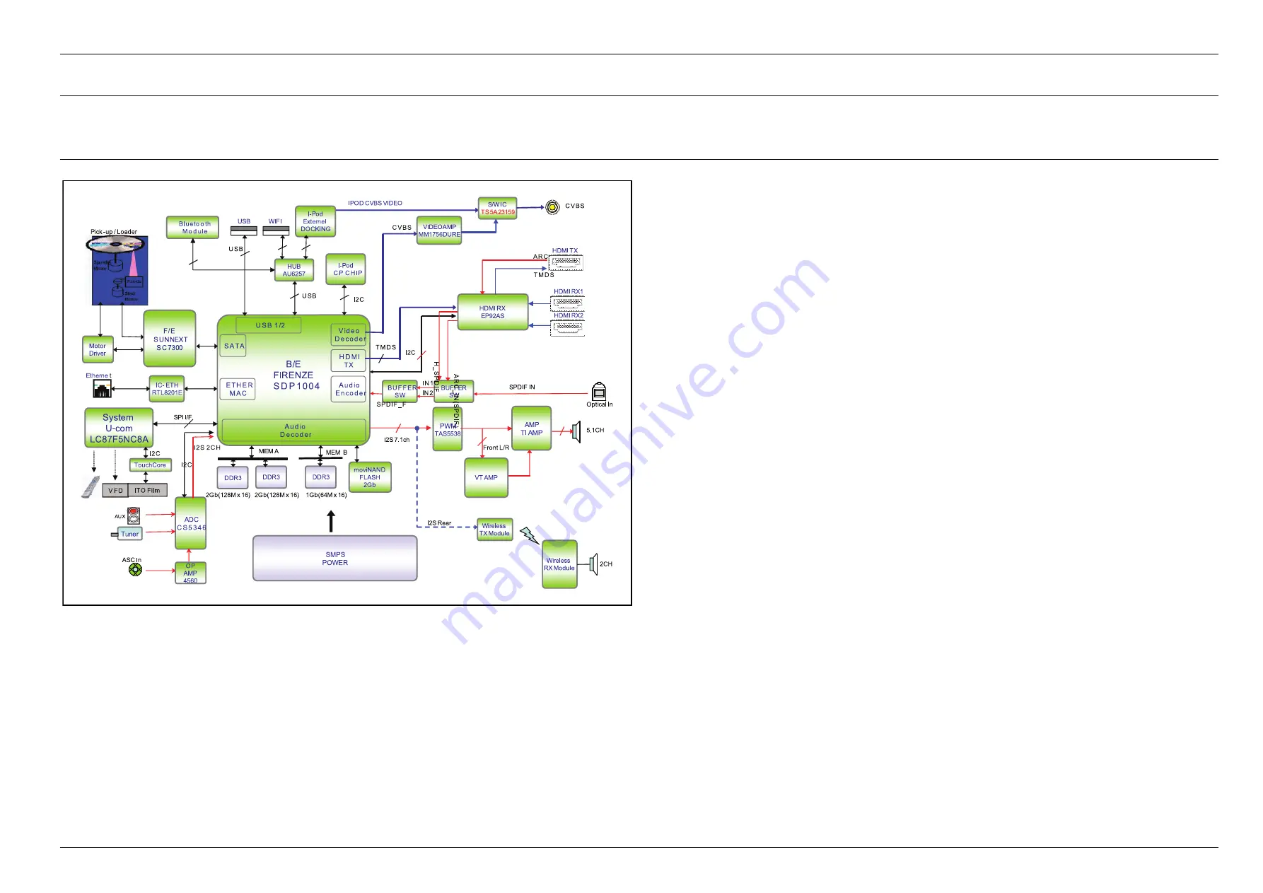
6.1. Overall Block Diagram
B
/E
FIRENZE
S D P 1 0 0 4
00000
00000
00000
V
id e o
D e c o d e r
0000000000000000
0000000000000000
0000000000000000
A
u d io
D e c o d e r
0000
0000
0000
E
TH E R
M AC
E
the rne t
00000
00000
00000
H
D M I
TX
M
otor
Drive r
000
000
000
000
S
ATA
D
DR3
D
DR3
D
DR3
2G b(128M x 16)
MEM A
MEM B
V
IDEO AMP
MM1756DURE
H
DMI TX
T
MD S
A
DC
C S 5 3 4 6
O
ptica l In
SPI I/F
S
ys te m
U-com
LC87F5NC8A
Pick -up / Loa de r
AUX
T
une r
I
-Pod
C P C H IP
00000000
00000000
U
S B 1 /2
S
MP S
P OWER
P
WM
TAS5538
I
2S 7.1ch
W
IFI
IPO D CVBS VIDEO
C
VBS
F
/E
S UNNEXT
S C 7300
I
-Pod
Exte rne l
DO CKING
W
ire le s s
TX Module
I
2S Re a r
W
ire le s s
RX Module
I2 C
U S B
S
/W IC
T
S 5A23159
H
DMI RX
EP92AS
H
DMI RX1
H
DMI RX2
B
UFFER
SW
O
P
AMP
4560
A
SC In
00000
00000
00000
A
u d io
E n c o d e r
S
PDIF IN
I
2 S 2 C H
m
oviNAND
FLASH
2G b
H
UB
AU6257
U
SB
U S B
I
C- ETH
RTL8201E
V F D
ITO F ilm
T
ouchCore
C
VBS
A
MP
TI AMP
5
.1CH
I
2C
I2 C
V
T AMP
F
ront L/R
2
CH
2G b(128M x 16)
1G b(64M x 16)
B
lu e to o th
Mo d u le
I2 C
AR C
T MD S
B
U F F E R
S W
I
N 1
IN 2
S
P D IF _ F
A
R
C
_
IN
(S
P
D
IF
)
H
_
S
P
D
IF
•
From DISC, RF signal is transmitted to BACKEND SDP93. The decoder SDP93 decodes the RF signal to VIDEO and AUDIO
DATA.
About Digital Video signal, HDMI goes to HDMI Repeater IC, EP92AS. it gets TMDS DATA from SDP93. HDMI IN signals go
to HDMI OUT through HDMI Repeater IC and Decoder IC.
•
HT-E6xxx series support 1 USB port. It is for USB File play like MP3, JPG, DivX and etc. iPod, iPhone are also supported.
•
About SDP93 Audio output, I2S datas go PWM IC (TAS5538) to convert PWM signals and then go to AMP IC (TAS5614) except
Front Ch. Front Ch signals go to Vaccum tube passing through LPF to convert analog signal from PWM signals and then analog
audio datas passed by vaccume tube go to AMP IC (TAS5613).
All of channel audio datas passed by AMP IC are amplitude and out to Speaker Jack by passing through LPF.
Copyright© 1995-2012 SAMSUNG. All rights reserved.
6-1
Summary of Contents for HT-E6759W
Page 62: ...5 PCB Diagram 5 2 FRONT PCB Top CN1 1 TP2 5 2 Copyright 1995 2012 SAMSUNG All rights reserved...
Page 73: ...5 PCB Diagram 5 7 USB PCB Bottom Copyright 1995 2012 SAMSUNG All rights reserved 5 13...
Page 76: ...5 PCB Diagram 5 9 VT PCB Bottom 5 16 Copyright 1995 2012 SAMSUNG All rights reserved...
Page 80: ...5 PCB Diagram 5 11 SMPS PCB Bottom 5 20 Copyright 1995 2012 SAMSUNG All rights reserved...


