Ch1 Precautions
Safety Precautions .......................................1-1
Servicing Precautions ..................................1-2
Precautions for Electrostatically
Sensitive Device (ESDs ...............................1-3
Special Precautions and Warning
Lables for Laser Products ............................1-4
Special Precautions for HDD .......................1-5
INDEX
Ch2 Product Description
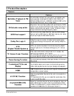
Features . . . . . . . . . . . . . . . . . . . . . . . . . .2-1
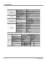
Specifications . . . . . . . . . . . . . . . . . . . . . .2-2
Accessories . . . . . . . . . . . . . . . . . . . . . . .2-3
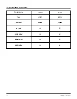
Specification Comparison . . . . . . . . . . . . .2-4
Ch3 Product Functions
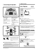
SPK connection ...........................................3-1
Main Functions.............................................3-2
New Functions .............................................3-3
Ch4 Adjustments
DVD flash Initialization & Update .................4-1
Ch5 How to disassemble
Separate CABINET-TOP ..............................5-1
Separate REAR-COVER..............................5-2
Separate CHASSIS-BACK...........................5-3
Separate PCB ..............................................5-5
Ch6 TroubleShooting
Main .............................................................6-1
Output ..........................................................6-2
In case of Power Protection .........................6-3
AMP Pre-Inspection relating to Power Protection..6-4
Ch7
Exploded Views and Parts List
HT-X250 Exploded View ..............................7-1
HT-X250 Parts List .......................................7-2
Ch9 Block Diagram
Block ............................................................9-1
Ch10 Wiring Diagram
Wiring Diagram ..........................................10-1
GND ...........................................................10-2
VDD............................................................10-3
SMPS .........................................................10-4
Ch11 PCB Diagram
MAIN PCB..................................................11-1
MAIN PCB Description ..............................11-2
SMPS-PCB ................................................11-4
Ch12 Schematic Diagram
MAIN ..........................................................12-1
KEY ............................................................12-9
SMPS .......................................................12-10
Ch13 Circuit Board Description
PCB Assy. Layout 1 (HT-X250/X200).........13-1
Functional Description (SMPS) .............13-2
Functional Description (Main,Front) ........13-4
Functional Description (Amp)................13-4
Ch14
Definition of Home Theater ........................14-1
Concept of Sound .............................14-2
Home Theater Sound Format ...............14-3
Home Theater Components .................14-4
Ch8 Electrical Parts List
Electrical Parts Lis .......................................8-1
Summary of Contents for HT-X250
Page 2: ... Samsung Electronics Co Ltd JAN 2007 Printed in Korea Code no AH68 000000 ELECTRONICS ...
Page 20: ...5 4 Samsung Electronics D Separate MAIN SET ...
Page 22: ...6 1 Samsung Electronics 6 TroubleShooting 1 Main ...
Page 23: ...Samsung Electronics 6 2 2 Output ...
Page 24: ...6 3 Samsung Electronics 3 1 In case of Power Protection ...
Page 25: ...Samsung Electronics 6 4 3 2 SMPS Ass y Power check ...
Page 26: ...6 5 Samsung Electronics 3 3 AMP Pre Inspection relating to Power Protection ...
Page 27: ...Samsung Electronics 6 6 4 FAN Error Check ...
Page 28: ...6 7 Samsung Electronics 5 FAN CHECK Error ...
Page 29: ...Samsung Electronics 6 8 6 1 Communication Failure ...
Page 30: ...6 9 Samsung Electronics 6 2 Voltage Failure ...
Page 31: ...Samsung Electronics 6 10 ...
Page 32: ...6 11 Samsung Electronics 6 3 Communication Failure ...
Page 33: ...Samsung Electronics 6 12 7 Checking out AMP PCB ...
Page 34: ...6 13 Samsung Electronics 8 AMP PCB Short Check flow ...
Page 47: ...9 1 Samsung Electronics 9 Block Diagram 1 Block ...
Page 48: ...Samsung Electronics 10 1 10 Wiring Diagram 1 Wire Sheet ...
Page 49: ...10 2 Samsung Electronics 2 GND ...
Page 50: ...Samsung Electronics 10 3 3 VDD ...
Page 51: ...10 4 Samsung Electronics 4 SMPS ...
Page 52: ...11 1 Samsung Electronics 11 PCB Diagram 1 MAIN PCB ...
Page 53: ...Samsung Electronics 11 2 2 MAIN PCB Description ...
Page 54: ...11 3 Samsung Electronics 2 MAIN PCB Description ...
Page 55: ...Samsung Electronics 11 4 3 SMPS PCB ...
Page 64: ...Samsung Electronics 12 9 This Document can not be used without Samsung s authorization 2 KEY ...
Page 66: ...13 1 Samsung Electronics 13 Circuit Board Description 1 PCB Assy Layout 1 HT X250 X200 ...
Page 67: ...Samsung Electronics 13 2 2 Functional Description SMPS Main Front ...
Page 68: ...13 3 Samsung Electronics 3 Functional Description Amp HDMI Video ...
Page 69: ...Samsung Electronics 13 4 4 1 MAIN PCB Block 4 2 MAIN PCB Connectors ...
Page 70: ...13 5 Samsung Electronics 5 MAIN PCB HDMI VIDEO OUT ...
Page 71: ...Samsung Electronics 13 6 6 1 SUB PCB Block 6 2 SUB PCB Connectors ...
Page 72: ...13 7 Samsung Electronics 7 AMP PCB Block ...


