Samsung Electronics
3-1
Disassembly & Reassembly
3. Disassembly & Reassembly
3-1 Overall Disassembly & Reassembly
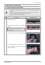
- Carefully follow the disassembly sequence described in the manual otherwise the product may
be damaged.
- Be sure to carefully read and understand the safety instructions before performing any work
because the IC chips on the PCB are vulnerable to static electricity.
- Assemble in the reverse order of disassembly.
No.
Description
Description Photo
1
1) Vertical Type Standing
2) Remove the 11 screws from the bottom of CABINET-
REAR.
Be careful not to make any scratches as you
remove them.
3) Remove the JACK-COVER from the CABINET-REAR.
4) Lift the CABINET-REAR up to separate Power Cord.
5) After disconnecting the Power Cord, lift the CABINET-
REAR up completely.
Summary of Contents for HW-C450
Page 16: ...3 4 Samsung Electronics MEMO ...
Page 35: ...Samsung Electronics 4 19 MEMO ...
Page 50: ...6 2 Samsung Electronics PCB Diagram 6 2 VFD PCB Top CN1 ...
Page 51: ...Samsung Electronics 6 3 PCB Diagram 6 3 VFD PCB Bottom ...
Page 52: ...6 4 Samsung Electronics PCB Diagram 6 4 KEY PCB Top ...
Page 53: ...Samsung Electronics 6 5 PCB Diagram 6 5 KEY PCB Bottom IC1 ...
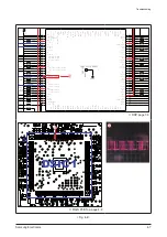
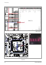
Page 57: ...Samsung Electronics 6 9 PCB Diagram 6 7 MAIN PCB Bottom TP3 TP5 DIIC1 DSIC3 PWIC1 IC1 ...
Page 58: ...6 10 Samsung Electronics PCB Diagram 6 7 1 Test Point Wave Form TP3 TP5 ...
Page 59: ...Samsung Electronics 6 11 PCB Diagram 6 8 SMPS PCB Top 1 CN2 CN1 ...
Page 61: ...Samsung Electronics 6 13 PCB Diagram 6 9 SMPS PCB Bottom ...
Page 62: ...6 14 Samsung Electronics MEMO ...
Page 72: ...7 10 Samsung Electronics MEMO ...


