background image

4-6

Samsung Electronics

Troubleshooting

C37

C21

C22

C24

C23

C25

D10

D9

C12

D6

D5

9

8

7

6

5

4

3

2

16

15

14

13

12

11

10

1

ADIC1

DSR5

DSL4

DSR6A

DSC4

DSC3

9

8

7

6

5

4

3

2

14

13

12

11

10

1

DSIC5

DSR6

DIR22

DIR23

DIR14
DIR12

DIR13

DIR19

DIR20

DIR21

DIR18

DIR17

DIR16

DIR15

9

8

7

6

5

4

30

3

29

28

27

26

25

24

23

22

21

20

2

19

18

17

16

15

14

13

12

11

10

1

DIIC1

DSR4

DSR1

DX1

DSC1

DSC2

DSR3

DSR2

DIC12

DIR11

DIC16

DIC17

DIL1

DIC11

DIC10

DIR9

DIR10

DIL2

DIC14

DIC13

ADL3

ADR6

ADR5

DSL1

EMC2

ADR9

ADR7

ADR8

ADR10

ADR11

ADC13

ADC11

ADC14

ADC12

ADC9

ADC10

ADC8

ADC7

ADC16

ADC15

R7

DIR5

DIC5

DIR7

DIC3

DIR1

DID3

DIC1

DIT1

DIR2

DIC6

DIR6

DIR8

DID1

DIC4

DIC8

DIC7

DID2

DIR3

DIC2

3

2

1

OP_JACK1

DIR4

DIT2

3

2

1

OP_JACK2

ADR4

ADR1

ADR2

ADR3

ADC6

BD1

ADC4

ADC3

ADC5

ADL2

ADC2

ADC1

9

8

7

6

5

4

3

2

11
10

1

A_JACK1

10V

4.7NF

DGND

100NF

16V

100NF

MLVS-0603-E08

1N4148WS

50V

100NF

50V

1N4148WS

75V

1/10W

1/10W

33OHM

AK4113VF

100NF

1/16W

10UF

16V

100NF

10UF 10V

100NF

16V

10NF

50V

10NF

1NF 50V

1/10W

15KOHM

2.2KOHM

100NF

50V

KTD1304

50V

16V

10V

10UF

22PF

DGND

100NF

100NF

1/16W

220PF

1/10W

22KOHM

100NF

50V

4.7OHM

10UF

10UF

DLR1130-1-B

GCC02-0077

DIR_MCLK

75V

12.288MHZ

100OHM

DGND

22PF

DGND

100OHM

75V

22KOHM

1/16W

2.2KOHM

1/16W

5000MA 0.01OHM

10UF

16V

10V

16V

DGND

1KOHM

15KOHM

AGND

1/16W

75V

22PF

33OHM

33OHM

33OHM

10UF

DIR_SYS_CLK

5000MA

DGND

D3.3V

50V

KTD1304

120OHM

1MOHM

1/10W

1/10W

270OHM

50V

DIR_CSN

100OHM

33OHM

1/16W
1/16W

100OHM

DIR_CLK

50V

50V

100NF

75V

1N4148WS

100PF

OPT_DET2

22KOHM

1/16W

100NF

1/16W

1/16W

1/16W

DIR_PDN

DIR_SYS_CLK

16V

33OHM

33OHM

100NF

1/16W

1/16W

1N4148WS

1/16W

33OHM

33OHM

1/16W

1/16W

1/16W

DIR_CDTI

DIR_CDTO

DIR_DATA0

DIR_MCLK

33OHM

33OHM

I_BCK

DIR_BCK

33OHM

1KOHM

100OHM

100OHM

W_MCLK

50V

1/16W

1/16W

0.01OHM

PS_SYS_CLK

1/10W

D3.3V

33OHM

2.2UF

33OHM

I_LRCK

DIR_ERF

DIR_LRCK

270OHM

1/10W

50V

50V

100PF

1/16W

22PF

33OHM

50V

100NF

DGND

MLVS-0603-E08

15KOHM

DIR_LRCK

22KOHM

4.7NF

OPT_DET1

100NF

0.05OHM

1/10W

DSP_MCLK

1/16W

4.7OHM

D3.3V

0.01OHM

5000MA

DGND

1N4148WS

ST_5.6V

DLR1130-1-B

AUX_SENS

22KOHM

22KOHM

220PF

10UF

100NF

100NF

AK_PDN

DIR_BCK

33OHM

1KOHM

1KOHM

10NF 16V

5000MA

A5V

1NF

50V

1NF

50V

1NF

DIF

CKS0

DGND

VD

LRCK
SDTO

VA

AGND

MCLK

VCOM

PDN

CKS2

SCLK

CKS1

AINL

AINR

Y4

GND

Y5
A4

Y3

A3

A5

Y2

A6

VCC

Y6

A2

Y1

A1

FS96/I2C

INT0

INT1

P/SN

IPS/RX6

RX5

RX4/DIF2

RX3/DIF1

RX2/DIF0

RX1

CM1/CDTI/SDA

CM0/CDTO/CAD1

OCKS0/CSN/CAD0

OCKS1/CCLK/SCL

AVSS

AVDD

MCKO2

MCKO1

R

PDN

XTO

XTI

LRCK

V/TX

BICK

DAUX

SDTO

TVDD

DVSS

DVDD

E

B

C

3

2

1

VOUT

GND

VCC

E

B

C

3

2

1

VOUT

GND

VCC

 INPUT JACK, page 7-5

DIIC1

DSIC3

PWIC1

IC1

 MAIN PCB Bottom, page 6-9

<Fig. 4-3>

1

1

1

Summary of Contents for HW-C450

Page 1: ...e GSPN see the rear cover for the more information CONTENTS 1 Precaution 2 Product Specification 3 Disassembly Reassembly 4 Troubleshooting 5 Exploded View Part List 6 PCB Diagram 7 Schematic Diagram Crystal Surround Air Track Model Name HW C450 Model Code HW C450 EDC HW C450 ...

Page 2: ...r domestic law GSPN Global Service Partner Network Area Web Site North America service samsungportal com Latin America latin samsungportal com CIS cis samsungportal com Europe europe samsungportal com China china samsungportal com Asia asia samsungportal com Mideast Africa mea samsungportal com Samsung Electronics Co Ltd Apr 2010 Printed in Korea ...

Page 3: ...verall Disassembly Reassembly 3 1 4 Troubleshooting 4 1 Checkpoints by Error Mode 4 1 4 2 Measures to be taken when the Protection Circuit operates 4 15 4 3 Initialization Update 4 17 5 Exploded View Part List 5 1 Exploded View 5 1 5 2 Speaker System 5 3 5 3 Electrical Part List 5 4 6 PCB Diagram 6 1 Wiring Diagram 6 1 6 2 VFD PCB Top 6 2 6 3 VFD PCB Bottom 6 3 6 4 KEY PCB Top 6 4 6 5 KEY PCB Bott...

Page 4: ...Contents 7 Schematic Diagram 7 1 Overall Block Diagram 7 1 7 2 KEY 7 2 7 3 VFD 7 3 7 4 U COM 7 4 7 5 INPUT JACK 7 5 7 6 DSP 7 6 7 7 PWM 7 7 7 8 IR AMP 7 8 7 9 SMPS 7 9 ...

Page 5: ...ces and Underwriters Laboratories UL Publication UL1410 59 7 With the unit completely reassembled plug the AC cord directly into a 120V AC outlet With the unit s power switched from the ON to the OFF position measure the current between a known ground and all exposed metal parts Known Grounds Earth Known Metal parts screwheads metal cabinets etc 5 Insulation Resistance Cold Check 1 With the unit s...

Page 6: ... AC power cord for damage Make sure that no wires or components touch thermally hot parts 8 Product Safety Notice Some electrical and mechanical parts have special safety related characteristics which might not be obvious from visual inspection These safety features and the protection they give might be lost if the replacement component differs from the original even if the replacement is rated fo...

Page 7: ...viced part has not been damaged 5 Check the insulation between the blades of the AC plug and accessible conductive parts examples metal panels input terminals and earphone jacks 6 Insulation Checking Procedure Disconnect the power cord from the AC source Connect an insulation resistance meter 500V to the blades of the AC plug The insulation resistance between each blade of the AC plug and accessib...

Page 8: ...mulation of electrostatic charge 3 Do not use freon propelled chemicals These can generate electrical charges that damage ESDs 4 Use only a grounded tip soldering iron when soldering or unsoldering ESDs 5 Use only an anti static solder removal device Many solder removal devices are not rated as anti static these can accumulate sufficient electrical charge to damage ESDs 6 Do not remove a replaceme...

Page 9: ...2 1 Product Specification 2 Product Specification 2 1 Product Feature 280W 80W x 2 120W 2 1ch Wireless Active DD DTS 1 analog 2 opticals Smart Volume II Virtual Surround Music News Movie Drama Game Sports Pass 2 Way 3 Spk ...

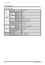
Page 10: ...Ibs Dimensions W x H x D Main unit 37 66 x 3 62 x 1 77 inches Subwoofer 6 89 x 13 78 x 11 61 inches Operating temperature range 41 F to 95 F Operating humidity range 10 to 75 AMPLIFIER Rated output power Main unit 80W CH 4Ω THD 10 1kHz Subwoofer 120W 4Ω THD 10 100Hz Input sensitivity impedance 450mV 20KΩ S N ratio analog input 70dB Separation 1kHz 70dB FREQUENCY RESPONSE Analog input 20Hz 20kHz 3d...

Page 11: ... Volume Smart Volume II Audio Up scale X X Power Bass X X Audio Decoding Dolby Digital Plus Dolby Digital Dolby Digital Dolby True HD N A N A DTS DTS HD HR MA DTS DTS Video Component out X X HDMI Out CEC X X HDMI Input X X Audio in out Mini Jack Audio In AUX1 3 5φ AUX1 3 5φ RCA Input X X Optical jack in Digital in 2 Headphone Headphone Jack 3 5Φ X X Tuner FM X X Preset Memory 15 15 Speaker Type Sa...

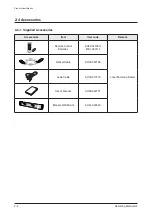
Page 12: ...m Item code Remark POWER TV POWER TV SOURCE VOL TV CH PASS NEWS MUSIC MUTE CINEMA O A INPUT POWER LINK AUTO MENU EXIT TOOLS INFO Remote Control Batteries AH59 02196G 4301 000116 Local Samsung Dealer Optical Cable AH39 00779A Audio Cable AH39 01077A User s Manual AH68 02273F Bracket Wall Mount AH61 02952A ...

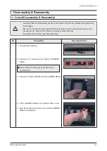
Page 13: ...fore performing any work because the IC chips on the PCB are vulnerable to static electricity Assemble in the reverse order of disassembly No Description Description Photo 1 1 Vertical Type Standing 2 Remove the 11 screws from the bottom of CABINET REAR Be careful not to make any scratches as you remove them 3 Remove the JACK COVER from the CABINET REAR 4 Lift the CABINET REAR up to separate Power...

Page 14: ...arate 3 cables FFC Cable from MAIN PCB 2 Separate 2 Speaker Wires from MAIN PCB 3 Separate the connection between MAIN PCB SMPS PCB 4 Remove 5 screws 3 1 Remove the screw and separate the Wireless Module 2 Separate the chassis from the front cover 3 Separate the VFD Assy MAIN PCB SMPS PCB ...

Page 15: ...Samsung Electronics 3 3 Disassembly Reassembly No Description Description Photo 4 1 Separate Speaker L R ...

Page 16: ...3 4 Samsung Electronics MEMO ...

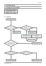
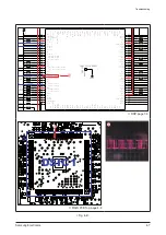
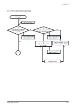
Page 17: ... power circuit of SMPS PCB Check the outputs of TRANS No Yes No The power does not turn on AC Cable check and replace Yes Yes Check if H 3 3V is measured at the pin 26 of the UIC1 when Main PCB power is turned on Replace the Micom UIC1 Replace the connector CN2 No Check the power 3V at MAIN PCB P_CON1 NO 18 Refer to wave pattern image of Fig 4 1 Refer to wave pattern image of Fig 4 2 1 Is there 5V...

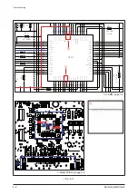
Page 18: ...16W 100NF 3 3KOHM 1 16W KEY_SDA 100NF WP MLVS 0603 E08 15KOHM 50V K MO 1 16W 1 16W 0OHM 50V 10V 16V 100NF MLVS 0603 E08 1 16W 100OHM 4 7KOHM 4 7KOHM M_ 3 3V 50V 10UF MI D5V 10KOHM 1 10W 2 2KOHM 0 01OHM 10OHM 4 7KOHM E M_ 3 3V 10UF 100NF 1KOHM 10NF 16V M 0W 4 7KO T A 4 7KOHM 1 10W 3 3KOHM 4 7KOHM 1 16W 10KOHM KEY_TEST KEY_RST D5V 1 16W 15KOHM 1 16W 1 16W 1 16W REM_DATA KEY_SCL 1 16W 100OHM ADC 2 AD...

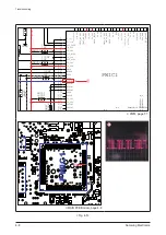
Page 19: ...4 3 2 19 18 17 16 15 14 13 12 11 10 1 PCON1 IRC2 IRR9 IRR10 IRR2 IRR7 IRR8 I IRC1 IRR1 IRR6 IRR5 I PVDD 25 GVDD 12V PVDD25V VFD_ 18V VFD_ 21 AGND ST_5 6V VP_ 27V 1 47KOHM D3 A5V 4 7OH A5V D5V AUDIO_R 10UF 4 7OHM 2 2KOHM 2 2KOHM 16V DGND 16V 10UF OHM 5 1 S_GND A5V 47KOHM OHM AUDIO_L 5 A5V IR AMP page 7 8 K_CON1 PCON1 SPK R SPK L MAIN PCB Top page 6 6 Fig 4 2 2 2 2 ...

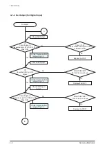
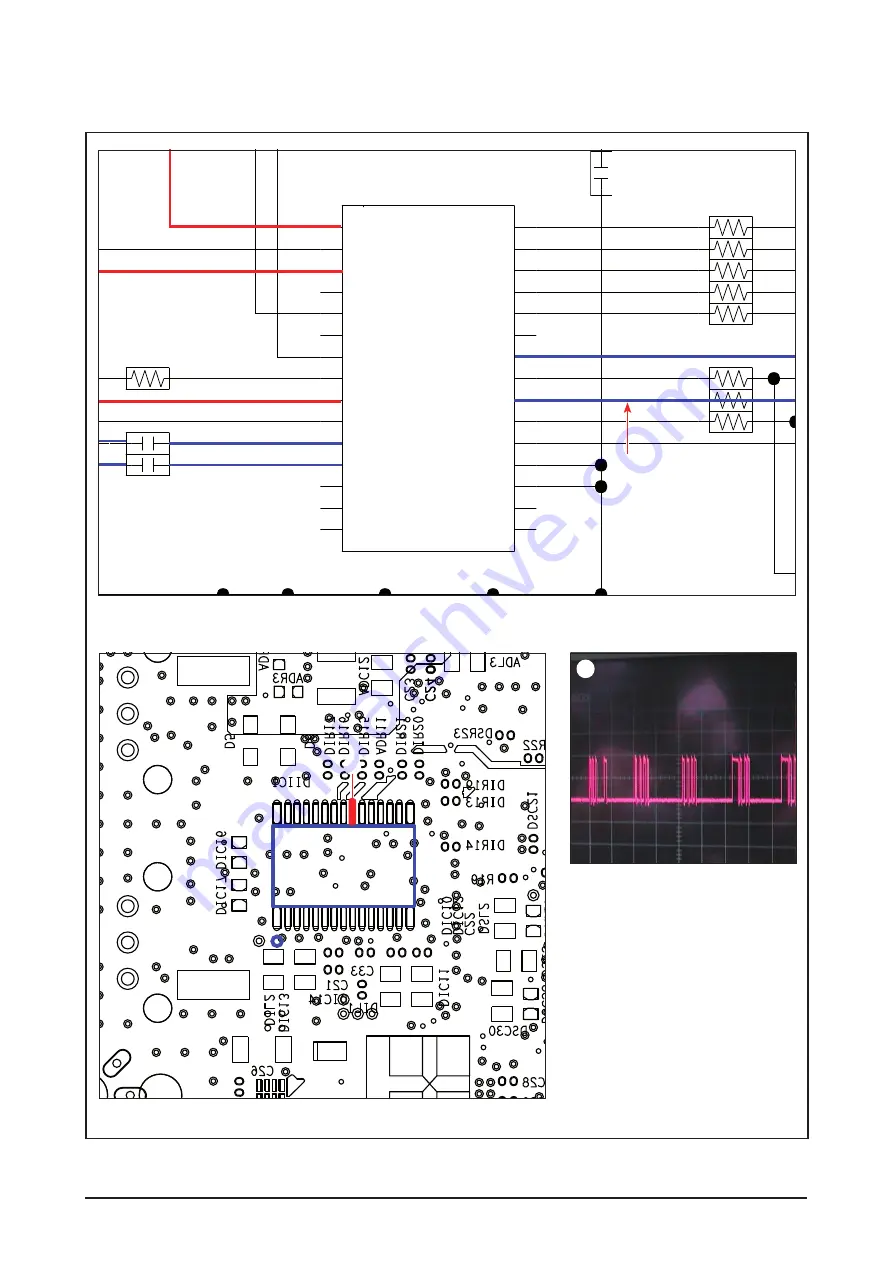
Page 20: ...e the DSIC1 Check DIR Output Check DSP Output Replace the PWIC1 No 3 Check if signal is measured at pin 15 of PWIC1 of the Main PCB Check PWM Input Output Refer to wave pattern image of Fig 4 3 Refer to wave pattern image of Fig 4 4 A Refer to wave pattern image of Fig 4 5 Check if 3 3V power is measured at pin 9 of DIIC1 of the Main PCB MAIN PCB DSIC1 No 142 144 clock check MAIN PCB PWIC1 No 4 10...

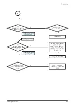
Page 21: ...n 3 18V pin 4 8 25V pin 10 13V pin 13 14 5V B No Yes No 5 Check the MAIN PCB SPK JACK1 2 pin 2 speaker output signal Check Speaker Output Refer to wave pattern image of Fig 4 6 Refer to wave pattern image of Fig 4 7 MAIN PCB AIC1 No 4 8 5V check No Change the MAIN PCB No Check the resistance SPK JACK 1 SPK JACK2 CABLE No Check the resistance SPK JACK 1 SPK JACK2 CABLE Yes ...

Page 22: ...10NF 15KOHM 50V 100NF 100OHM 33OHM 1 16W 1 16W 100OHM 75V 1N4148WS 1 1 1 16V 33OHM 33OHM 33OHM 33OHM 1 1 1 33OHM 33OHM 33OHM 1KOHM 100OHM 100OHM 1 1 1 10W 33OHM 2 2UF 33OHM 50V DGND 100NF 0UF NF 100NF 33OHM 1KOHM 1KOHM 10NF 16V 5000MA A5V 1NF 50V 1NF DIF CKS0 DGND VD LRCK SDTO VA AGND MCLK VCOM PDN CKS2 SCLK CKS1 AINL AINR FS96 I2C INT0 INT1 P SN IPS RX6 RX5 RX4 DIF2 RX3 DIF1 RX2 DIF0 RX1 CM1 CDTI...

Page 23: ... 33OHM 33OHM 10KOHM 16V 33OHM 10NF 16V DSP_MCLK 6 3V 33OHM 100NF 16V 16V 10KOHM 16V 16V 10KOHM 100NF 16V 100NF 100NF 16V 10KOHM 100NF 100NF F_TMS 1KOHM C 33OHM 33OHM 33OHM 100NF 100NF 16V 16V 100NF 16V F_TDI F_NTRST 100NF 16V 33OHM 16V 100NF 16V 100NF 33OHM 100NF 16V 100NF 16V 100NF 16V 100NF 16V 16V 16V 10KOHM 100NF 5000MA 0 01OHM F_TDO 10UF 22NF 100NF 100NF 10UF DGND 16V 16V 16V AFSR0 ACLKX0 AHC...

Page 24: ...7UF 100NF 10UF 100 16V 47UF 6 3V 47UF IO_VSS DVSS PWM1_P PWM1_M PWM_HP_R_M IO_VDD IO_VSS PWM_SWL_P PWM_SWL_M DVSS DVDD MIC_SDIN MIC_LRCK MIC_BCK MIC_MCLK IO_VDD IO_VSS EXT_MUTE SSDIN3 SSDIN2 DVDD SCK SCL SO SDA EPD_ENA SLRCK SBCK MSDIN3 MSDIN2 IO_VDD PWM3_P PWM3_M IO_VSS MLRCK MBCK IO_VDD IO_VSS PLL_AVSS IO_VSS PLL_AVDD IO_VSS IO_VDD PLL_DVDD PLL_DVSS IO_VSS NC NC IO_VSS IO_VDD NC NC IO_VSS RECOUT...

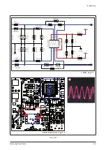
Page 25: ...S 0OHM 50V 0OHM 1 10W 75V 2 7NF M 1 5KOHM AGND AGND 2 7NF 2 7NF 820OHM 2 7NF AUDIO_L 1 5KOHM M 1 5KOHM 50V 680PF M 2 7NF 1 5KOHM AUDIO_R 10OHM 10OHM M 2KOHM 2 7NF 3KOHM 2KOHM 2 7NF 820OHM 2 7NF 820OHM 0OHM 680PF 50V A5V 820OHM 680PF 50V BA4560F 100NF 50V 100NF A5V 50V 680PF 6 3V 47UF AGND 6 3V 47UF 1N4148WS 75V D 3KOHM IN2 VEE OUT2 VCC IN2 IN1 IN1 OUT1 PWM page 7 7 SIC5 IPIC1 AIC1 U1 MAIN PCB Bott...

Page 26: ... 2 1 SPK1 PVDD25V PVDD25V PVDD 25V 100NF 50V 50V 22KOHM 6645 1OHM 27KOHM 1OHM 27KOHM 100V 100NF 2 2NF 50V 2 2NF 50V 2 2KOHM 10OHM 470NF 100V DCP 100NF 1 10W 1OHM UNDEFINED F6645 S_GND UNDEFINED DCP 68KOHM 470NF 100V 100NF 100V 2 2KOHM 1 10W S_GND 68KOHM S_GND 2 2NF 50V 50V 100V 50V 100NF 100NF 10KOHM S_GND 1OHM 100NF 10OHM 6645 S_GND S_GND 100NF 50V 100NF 100V S_GND S_GND 50V F6645 5267 02A 5267 0...

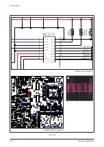
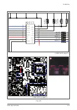
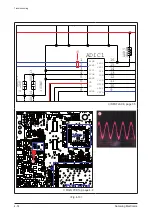
Page 27: ... of the Main PCB Yes 2 Check the CLK at pin 10 of ADIC1 of the Main PCB 3 Check ADIC1 pin 1 2 out in signal Check the power 5V pin 6 of ADIC1 on the Main PCB No Yes No Check ADC Output A Refer to wave pattern image of Fig 4 9 Refer to wave pattern image of Fig 4 10 Refer to wave pattern image of Fig 4 8 Yes No No Replace the ADIC1 ...

Page 28: ... ADR9 ADR7 ADR8 ADR10 ADR11 ADC13 ADC14 ADC16 50V 1N4148WS 75V 100NF AGND 75V 1N4148WS 33OH 33OH 33OH 33OH 50V 100NF 100NF 100NF 33OH 1KOHM 1KOHM 10NF 16V 5000MA 1NF DIF CKS0 DGND VD LRCK SDTO VA AGND MCLK VCOM PDN CKS2 SCLK CKS1 AINL AINR INPUT JACK page 7 5 W_CON1 DSIC5 UIC1 DSIC1 ADIC1 MAIN PCB Top page 6 6 Fig 4 8 1 1 1 ...

Page 29: ...5 DS EM ADR9 ADR7 ADR8 ADR10 ADR11 50V 1N4148W 75V 100N AGND 75V 1N4148 33OHM 33OHM 33OHM 33OHM 50V 100NF 100NF 100NF 33OHM 1KOHM 1KOHM 10NF 16V 5000MA 1NF DIF CKS0 DGND VD LRCK SDTO VA AGND MCLK VCOM PDN CKS2 SCLK CKS1 AINL AINR INPUT JACK page 7 5 W_CON1 DSIC5 UIC1 DSIC1 ADIC1 MAIN PCB Top page 6 6 Fig 4 9 2 2 2 ...

Page 30: ...DR ADR ADR ADR1 ADR1 ADC13 ADC11 ADC14 ADC12 ADC16 ADC15 R7 1N4148WS 75V 100NF 4 7OHM 10UF AGND 75V 1N4148WS 2 2UF 50V 100NF 10UF 100NF 100NF 1KOHM 1KOHM DIF CKS0 DGND VD LRCK SDTO VA AGND MCLK VCOM PDN CKS2 SCLK CKS1 AINL AINR INPUT JACK page 7 5 W_CON1 DSIC5 UIC1 DSIC1 ADIC1 MAIN PCB Top page 6 6 Fig 4 10 3 3 3 ...

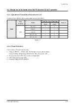
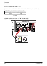
Page 31: ...Location Pin No Protection Circuit Operation Remark Open Short CN2 D5V 5 6 A5V 7 A5V 9 25V 11 12 25V 15 16 Table 4 1 4 2 2 Power Protection The Condition of Power Protection Active 1 Voltage of SMPS s PVDD 25V 25V is higher or lower than standards Normal Condition Voltage Range PVDD 25V 25V about 25V 25V 2 Over current occurs to FET Over output or Output short 3 FET s temperature exceed 150 C 4 No...

Page 32: ... problems at the AMP PCB you can check the PCB without disassembling the set Caution Do not connect the power cord during the test Resistance using Tester F R CH 10kΩ Table 4 2 In case of large difference with above value AMP PCB has a problem SPEAKER OUTPUT IPIC1 K_CON1 AIC1 PCON1 U1 SPK R SPK L GND ...

Page 33: ...button on the remote control 3 After blinking Standby red LED the version will be displayed on the VFD 4 3 2 How to initialize 1 Using the remote control 1 Turn power off 2 Press for 5 seconds MUTE button in remote 3 Stanby LED becomes OFF and Volume LED is lighted 4 If Volume LED becomes OFF and Stand by LED becomes ON initialization is ended ...

Page 34: ...hether it is a Micom Touch Key DSP or Wireless update you can see the following VFD display Case 1 Micom Update M 0 M 100 OK Case 2 Touch Key Update T 0 T 100 OK Case 3 DSP Update D 0 D 100 OK Case 4 Wireless Update The Sound Bar W 0 W 100 OK 4 Step 4 Sub woofer wireless update After updating Sound bar wireless the Sub woofer updates automatically When the Blue and Red LED blink it means the the S...

Page 35: ...Samsung Electronics 4 19 MEMO ...

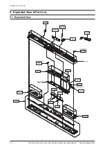
Page 36: ...ed View Part List This Document can not be used without Samsung s authorization 5 Exploded View Part List 5 1 Exploded View AC169 HWN01 W391 T0279 W391 W390 P001A M0014 W275 MOD2 MF05A MK01A SPKLE SPKRI T0268 FH01A FL261 FL261 FL261 ...

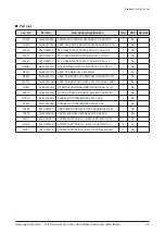
Page 37: ...SECC T2 0 13 53 5 1 SA M0014 AH94 02511A ASSY PCB MAIN HW C450 MAIN 1 SA MF05A AH94 02414A ASSY PCB FRONT VFD ASSY HW C450 ASSY VFD 1 SA MK01A AH94 02415B ASSY PCB KEY TOUCH HW C450 TOUCHKEY ASSY 1 SA MOD2 AH40 00164A RF MODULATOR NAM WM51 DSSS 10dBm 3 3 5V 1 SA P001A AH44 00225A DC VSS HP HW C450 HECK HWC450 F AC DC 50 1 SA SPKLE AH81 05688A SPEAKER SYSTEM BAR SPK LEFT SPK 1 SA SPKRI AH81 05689A ...

Page 38: ...ed View Part List This Document can not be used without Samsung s authorization 5 2 Speaker System Part List Loc No Part No Description Specification Qty SNA Remark Wireless Subwoofer AH91 00077J ASSY SPEAKER 1 SA Wireless Subwoofer ...

Page 39: ...UCH HW C450 TOUCHKEY ASSY 1 SA MR112 2007 000309 R CHIP 10ohm 5 1 10W TP 1608 2 SNA MROP1 2007 000090 R CHIP 10Kohm 5 1 10W TP 1608 1 SA PC69 2203 006818 C CER CHIP 47000nF 20 6 3V X5R 3216 1 SA PC7 2203 002709 C CER CHIP 100nF 80 20 16V Y5V 1005 7 SA PPC2 2203 005148 C CER CHIP 100nF 10 16V X7R TP 1608 5 SNA R104 2007 000148 R CHIP 10Kohm 5 1 16W TP 1005 3 SA R105 2007 000138 R CHIP 100ohm 5 1 16...

Page 40: ...50 SOUND SPK RUBBER DA 1 SNA SPEAKE AH81 05694A SPEAKER PART HT C450 SOUND SPK RUBBER DU 1 SNA SPEAKE AH81 05684A SPEAKER PART BAR SPK TWEETER 1 SNA SPEAKE AH81 05686A SPEAKER PART BAR SPK INPUT WIRE_L 1 SNA SPEAKE AH81 05695A SPEAKER PART HT C450 SOUND SPK SCREW 1 SNA SPEAKE AH81 05683A SPEAKER PART BAR SPK WOOFER 8 1 SNA SPEAKE AH81 05693A SPEAKER PART HT C450 SOUND SPK RUBBER DA 1 SNA SPEAKE AH...

Page 41: ...39 R CHIP 47Kohm 1 1 10W TP 1608 2 SNA AR49 2007 000140 R CHIP 1Kohm 5 1 16W TP 1005 10 SNA AVC08 2203 002398 C CER CHIP 22nF 10 50V X7R 1608 1 SNA AVR51 2007 000083 R CHIP 3Kohm 5 1 10W TP 1608 2 SNA C 2401 004704 C AL 470uF 20 50V TP 16x12 5mm 5mm 2 SNA C102 2203 006158 C CER CHIP 100nF 10 16V X7R TP 1005 87 SA C125 2203 006361 C CER CHIP 10000nF 10 10V X5R TP 2012 18 SA C134 2203 000257 C CER C...

Page 42: ...R CHIP 390ohm 5 1 10W TP 1608 2 SA MR36 2007 000153 R CHIP 22Kohm 5 1 16W TP 1005 5 SA MROP1 2007 000090 R CHIP 10Kohm 5 1 10W TP 1608 7 SA OTR1 2007 001292 R CHIP 33ohm 5 1 16W TP 1005 33 SNA P803T 1404 001483 THERMISTOR PTC 470ohm 50 32V TP 1 SA PC43 2203 000233 C CER CHIP 0 1nF 5 50V C0G TP 1005 2 SNA PC69 2203 006818 C CER CHIP 47000nF 20 6 3V X5R 3216 10 SA PIC2 1203 002220 IC POSI ADJUST REG...

Page 43: ... 18pF 50 1 SNA ZC14 2203 000626 C CER CHIP 0 022nF 5 50V C0G 1608 4 SNA ZIC3 1107 001709 IC FLASH MEMORY MX25L1605DM2I 12G 16Mbit 1 SNA ZR24 2007 000109 R CHIP 1Mohm 5 1 10W TP 1608 1 SA ZRN10 2011 001261 R NETWORK 33ohm 5 1 16W L CHIP 8P TP 2 1 SA ZVL3 3301 001495 BEAD SMD 120ohm 2012 2500mA TP 115ohm 10 2 SA 0202 001768 SOLDER BAR HSE 16 S60S 20 D3 SN 0 5CU 0 2 524 SNA 0204 002514 THINNER TS4500...

Page 44: ... 1 SNA AH68 02273H MANUAL USERS HW C450 EDC GRE ROM BUL SER 1 SNA AH68 50254B LABEL SERIAL T0 1 L10 W42 SME SEHZ 1 SNA AK68 01811H LEAFLET WARRANTY CARD comm Samsung Lang1 1 SNA EC19 AH39 01077A CBF CABLE ALDSX185 HT WS1 1P 2P 1500mm D 1 SC EC02 AH39 00925B INTERFACE CABLE OPTICAL HT BD1250 OPTICA 1 SA AH92 03320A ASSY LABEL HW C450 XAA EU W W 1 SNA CCM1 AH68 01929H LABEL RATING ALL ELS SILVER PET...

Page 45: ...P TP 5x11 5 1 SNA C 2401 000970 C AL 22uF 20 50V WT TP 5x11 5 1 SNA C 2401 000287 C AL 100uF 20 16V WT TP 6 3x11 5 2 SA C 2402 001254 C AL SMD 10uF 20 50V WT TP 6 3x5 2mm 1 SA C 2402 001081 C AL SMD 100uF 20 25V WT TP 8 3x8 3x10 1 SA C 2401 004447 C AL 680uF 20 50V LZ TP 12 5x25mm 5mm 2 SNA C 2401 003069 C AL 470uF 20 50V WT TP 10x20mm 5 2 SA C 2401 004723 C AL 220uF 20 450V BK 30 25 10mm 1 SNA C1...

Page 46: ...TR SMALL SIGNAL KSC1623 L NPN 200mW SOT 4 SA LF2_1 AH29 00016B FILTER LINE HT Z320 TR16 4 0mH 0 08 4 0m 2 SA MOD1 AH40 00164B RF MODULATOR NAM WM52 DSSS 10dBm 3 3 5V 1 SA MPIC1 AH14 10003E IC KIA7812PI TO 220 1 SA MR112 2007 000309 R CHIP 10ohm 5 1 10W TP 1608 3 SNA MR122 2007 000094 R CHIP 22Kohm 5 1 10W TP 1608 2 SNA MR19 2007 000087 R CHIP 6 8Kohm 5 1 10W TP 1608 4 SA MR8 2007 000503 R CHIP 2 2...

Page 47: ...AH94 02478B ASSY PCB LED LED ASSY HW C450 LED ASSY 1 SNA SP03A AH96 00273P ASSY SPEAKER P SYSTEM HW C450 SUBWOOFER 1 SNA ST026 AH61 03080A FOOT PS WC450 HIPS Dia 23mm BLACK 2mm 1 SNA T0086 1203 005211 IC PWM CONTROLLER ICE3BR4765J DIP 8P 9 4 1 SA T0086 1203 006090 IC PWM CONTROLLER ICE2QS03 DIP 8P 9 52x6 1 SA T0087 1203 003695 IC POSI FIXED REG NCP1117ST33T3G SOT 22 1 SA T0087 1203 001006 IC POSI ...

Page 48: ...6 3x5 1 SNA 2201 002070 C CERAMIC DISC 1 5nF 20 400V Y5U 11x6mm 1 SNA 2301 001730 C FILM MPEF 470nF 10 275V BK 11x18x18 5 1 SNA 2301 001760 C FILM MPEF 100nF 10 250V TP B5xH13 5x1 1 SNA 2301 001788 C FILM MPEF 220nF 10 275V BK 18x7 5x13 1 SA 2402 001166 C AL SMD 22UF 20 50V GP TP 6 3MMX5 4MM 1 SNA 3601 001496 FUSE RADIAL LEAD 250V 5A TIME DELAY RESI 1 SNA AH26 00372A TRANS SWITCHING ER3541 SWA 500...

Page 49: ...14 PR_LRCK 11 11 15 15 W_TSD2 12 12 16 16 13 13 17 17 14 14 18 18 15 15 19 19 I_POD DATA 16 16 20 20 I_LRCK 17 17 21 21 I_BCK 18 18 22 22 19 19 23 23 WP 24 24 DGND DGND DGND VFD_CE VFD_CLK ST_5 6 DGND KEY_SCL KEY_SDA DGND KEY_RST KEY_TEST REM_DATA M_ 3 3V M_ 3 3V VP_ 27V VFD_ 21V VFD_ 18V VFD DATA DGND VFD_RST VP_ 27V VFD_ 21V VFD_ 18V PVDD25V PVDD25V S_GND S_GND PVDD 25V PVDD 25V GVDD 12V A5V AGN...

Page 50: ...6 2 Samsung Electronics PCB Diagram 6 2 VFD PCB Top CN1 ...

Page 51: ...Samsung Electronics 6 3 PCB Diagram 6 3 VFD PCB Bottom ...

Page 52: ...6 4 Samsung Electronics PCB Diagram 6 4 KEY PCB Top ...

Page 53: ...Samsung Electronics 6 5 PCB Diagram 6 5 KEY PCB Bottom IC1 ...

Page 54: ...6 6 Samsung Electronics PCB Diagram 6 6 MAIN PCB Top 1 TP6 TP1 2 3 4 5 6 TP2 TP4 TP7 TP7 TP8 TP9 TP10 W_CON1 DSIC5 IPIC1 K_CON1 UIC1 AIC1 PCON1 DSIC1 ADIC1 U1 SPK R SPK L ...

Page 55: ...al Control Pin No Signal 1 VP_ 27V 2 VFD_ 21V 3 VFD_ 18V 4 PVDD25V 5 PVDD25V 6 S_GND 7 S_GND 8 PVDD 25V 9 PVDD 25V 10 GVDD 12V 11 A5V 12 AGND 13 A5V 14 D5V 15 D5V 16 DGND 17 DGND 18 POWER_ON 19 ST_5 6V 5 SPK R Front R CH Output Pin No Signal 1 FR OUT 2 GND 1 W_CON1 Wireless Control Pin No Signal 1 D5V 2 D5V 3 OPEN 4 OPEN 5 W_IRQ 6 DARR_RST 7 W_SCL 8 W_SDA 9 OPEN 10 OPEN 11 W_MCLK 12 DGND 13 PT_BCK...

Page 56: ...6 8 Samsung Electronics PCB Diagram TP1 TP2 6 6 2 Test Point Wave Form TP4 TP6 TP7 TP8 TP9 TP10 ...

Page 57: ...Samsung Electronics 6 9 PCB Diagram 6 7 MAIN PCB Bottom TP3 TP5 DIIC1 DSIC3 PWIC1 IC1 ...

Page 58: ...6 10 Samsung Electronics PCB Diagram 6 7 1 Test Point Wave Form TP3 TP5 ...

Page 59: ...Samsung Electronics 6 11 PCB Diagram 6 8 SMPS PCB Top 1 CN2 CN1 ...

Page 60: ...ectronics PCB Diagram 6 8 1 Pin Connection 1 CN2 Power Signal Control Pin No Signal 1 ST_5 6V 2 P_ON 3 GND 4 GND 5 D5V 6 D5V 7 A5V 8 GND 9 A5V 10 GVDD 11 25V 12 25V 13 GND 14 GND 15 25V 16 25V 17 VFD 18 VFD 19 VP 27V ...

Page 61: ...Samsung Electronics 6 13 PCB Diagram 6 9 SMPS PCB Bottom ...

Page 62: ...6 14 Samsung Electronics MEMO ...

Page 63: ...odule TX Module F ROM AKM AK5358 ADC DRIVE IC TOUCH KEY IC OP AMP 4558 Buffer Explore EPF005N U COM TI DSP Solution Main Block Diagram TI DSP Solution Main Block Diagram SMPS Main System uses Digital Signal Processor TMS320DA788B There are main circuit blocks such as AMP DSP POWER etc All displays is registered by LED Serial Interface between Ics is operated with various protocol over the whole sy...

Page 64: ... R16 R14 R12 R10 C4 C2 C3 R4 C1 100NF DGND KEY_TEST ST5V 1 16W KEY_SCL KEY_SDA ST5V 100OHM 100OHM 1 16W KEY_TEST ST5V 160KOHM 100NF 100OHM MLVS 0603 E08 100OHM 100OHM MLVS 0603 E08 50V MLVS 0603 E08 50V 560OHM DGND ST5V ST5V 10KOHM 1 16W 100OHM 10KOHM 16V DGND 100NF 50V MLVS 0603 E08 50V 160KOHM DGND KEY_RST KEY_RST 560OHM 100OHM 100NF DGND 560OHM DGND 560OHM 1 16W 10KOHM 249KOHM 100OHM KEY_SCL 16...

Page 65: ...KOHM TP1 V RST 16V 1KOHM D1 50V 3 47OHM VFD 1 10W DGND 100OHM 100OHM C11 VFD_RST C10 D3 3V 100NF 16V 6 3V 47UF 50V 68PF 5000MA 0 01OHM 68PF 50V 16V 100NF VFD_CE 50V D3 3V 50V 50V 50V 50V 100NF DGND VFD 10OHM DGND 10UF 10V 100NF DGND 100NF VFD 0 01OHM 5000MA BD1 FC1 FR7 1 2 MGND1 MGND2 R5 R4 R11 R7 R6 C4 CN2 1 11 12 13 14 15 16 17 18 19 2 20 21 22 23 24 3 4 5 6 7 8 9 C1 C5 R8 R9 R10 C7 CN1 1 10 11 ...

Page 66: ...VFD_CE VFD_CLK 1 10W 75V 1N4148WS 4 7KOHM 10PF ST_5 6V 16V VFD_DATA 1 10W 10MOHM 5000MA 1 16W 22KOHM DTA124ECA 16V 0 01OHM 16V DGND DGND 1N4148WS 100OHM 100OHM KEY_RST 1KOHM 100OHM 100NF 16V 100OHM 1KOHM 100OHM 0OHM W_IRQ POWER_ON 1 10W 1N4148WS 1 16W 100OHM DGND MLVS 0603 E08 4 7KOHM 1 16W 100NF 3 3KOHM 1 16W KEY_SDA 75V 100NF WP MLVS 0603 E08 15KOHM 50V DSP_CLK DSP_SIMO OPT_DET2 50V D5V DGND 1 1...

Page 67: ...DIR_MCLK 75V 12 288MHZ 100OHM DGND 22PF DGND 100OHM 75V 22KOHM 1 16W 2 2KOHM 1 16W 5000MA 0 01OHM 10UF 16V 10V 16V DGND 1KOHM 15KOHM AGND 1 16W 75V 22PF 33OHM 33OHM 33OHM 10UF DIR_SYS_CLK 5000MA DGND D3 3V 50V KTD1304 120OHM 1MOHM 1 10W 1 10W 270OHM 50V DIR_CSN 100OHM 33OHM 1 16W 1 16W 100OHM DIR_CLK 50V 50V 100NF 75V 1N4148WS 100PF OPT_DET2 22KOHM 1 16W 100NF 1 16W 1 16W 1 16W DIR_PDN DIR_SYS_CLK...

Page 68: ...000MA 0 01OHM 10NF MA11 33OHM DSP_RST DSP_SOMI 100NF 33OHM 33OHM 33OHM 33OHM 10KOHM 16V 33OHM 10NF 16V DSP_MCLK 6 3V 47UF 6 3V DGND 33OHM 33OHM 100NF 16V 16V 10KOHM 16V 16V 10KOHM 100NF 16V 100NF 100NF 16V 100NF 100NF 100NF 100NF DIR_DATA0 10KOHM 100NF 100NF F_TMS PT_BCK 33OHM MA3 MA5 1KOHM DSP_SIMO CAS_P 33OHM 33OHM 33OHM 100NF I_POD_DATA 100NF 16V 16V 100NF SFDI 16V CLK_P DQM1_P MD10 MD11 MD14 M...

Page 69: ...100NF 16V 50V 680PF 1 8KOHM 2 7NF 100NF 16V 50V 16V 100NF 1 5KOHM DGND PWM_FR_P 16V 100NF 10KOHM AUDIO_R 10OHM 10OHM 100NF 1 8KOHM 2KOHM 2 7NF 100OHM PS_EXT_MUTE 16V 100NF 50V 16V 16V 100NF 16V 16V 16V 100NF DGND 100NF 3KOHM 2KOHM 2 7NF 820OHM 2 7NF PWM_FR_N 100NF 820OHM 0 01OHM 0 01OHM PT_BCK 47OHM 47OHM 10UF DGND PS_TSD0 PWM_FR_P PWM_FR_N PWM_FL_N PWM_FL_P 0OHM 680PF 50V 100NF 16V DGND DGND A5V ...

Page 70: ... 50V 50V 22KOHM AGND 10UF 50V 10NF 1 5KOHM 5 6KOHM 4 7KOHM ST_5 6V 19 217 R6C AL1M2VY 3T VP_ 27V 100NF 50V 470UF 1 5OHM 100NF 50V 50V S_GND 47KOHM 390OHM 1 10W 1 10W IRF6645 1OHM 27KOHM 1OHM 50V 100NF 100NF 50V 100KOHM 150V PRF21BB471QB5RA 1KOHM 330OHM 12KOHM 10OHM 1 10W 27KOHM 100V 100NF 10OHM 2 2NF 50V 2 2NF 50V 2 2KOHM 10OHM 470NF 100V DCP 47NF 25V 1 10W 10KOHM MMBT2222A CSD_DISCHARGE 22OHM A5V...

Page 71: ... D6 HS1G EC13 33uF 63V NXB 6 3X11 1 2 RS18 NC S12 EC4 33uF 63V NXB 6 3X11 EC14 100uF 35V NXB 6 3X11 1 2 RS22 470 S12 EC6 33uF 450V KXJ 16X20 ZDS1 MMSZ5222 1 2 RS12 22K S12 1 2 RS19 220 S12 ZDS3 MMSZ5255 1 2 RS21 4 7K 1 2 3 QA3 MMBT2907 1 2 D7 BAV20W V 1 3 2 U5 KA7812 1 2 D8 SF35G 1 2 D9 SF35G 12 CS7 330pF 1KV 1 2 CS9 330pF 1KV 1 3 2 QA1 MMBT2222 1 2 RS20 4 7K 1 2 CS10 NC 1 2 RSA1 10 S12 BA FB CS D...

Page 72: ...7 10 Samsung Electronics MEMO ...

Reviews: