background image

T A B L E   O F   C O N T E N T S

I N S T A L L A T I O N   S E C T I O N

PART

DESCRIPTION

PAGE

INSTALLATION WARNINGS

 ................................................................i-ii

1

SITE REQUIREMENTS

.................................................................... 1.1

2

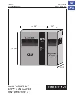
INSTALLATION OF BASIC KSU AND EXPANSION CABINET

2.1

UNPACKING AND INSPECTION ................................................... 2.1

2.2

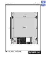
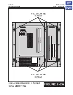
KEY SERVICE UNIT INSTALLATION ............................................. 2.1

2.3

EXPANSION CABINET INSTALLATION ......................................... 2.1

2.4

GROUNDING ................................................................................ 2.2

2.5

MDF CABLING .............................................................................. 2.4

2.6

POWER CONNECTIONS .............................................................. 2.4

3

INSTALLING PRINTED CIRCUIT CARDS

3.1

iDCS MEM3 CARD ........................................................................ 3.1

3.2

iDCS MEM4 CARD ........................................................................ 3.1

3.3

2 SLI CARD .................................................................................... 3.1

3.4

SMISC1 CARD ............................................................................... 3.1

3.5

SMISC2 CARD ............................................................................... 3.2

3.6

2 X 4 DLI CARD ............................................................................. 3.2

3.7

S8DLI CARD .................................................................................. 3.2

3.8

2 X 4 SLI CARD ............................................................................. 3.2

3.9

S8SLI CARD .................................................................................. 3.2

3.10

S3TRK CARD ................................................................................. 3.2

3.11

S6TRK CARD ................................................................................. 3.3

3.12

2 E&M 4 DLI CARD ........................................................................ 3.3

3.13

S4BRI CARD .................................................................................. 3.4

3.14

iDCS TEPRI CARD ......................................................................... 3.4

3.15

SPLL DAUGHTER BOARD ............................................................ 3.6

3.16

MODEM CARD .............................................................................. 3.6

3.17

ITMC .............................................................................................. 3.6

iDCS 100

INSTALLATION

TECHNICAL MANUAL

TABLE OF CONTENTS   JUNE 2002

HOME

PAGE

Table of

Contents

Summary of Contents for iDCS 100

Page 1: ...CABLING 2 4 2 6 POWER CONNECTIONS 2 4 3 INSTALLING PRINTED CIRCUIT CARDS 3 1 iDCS MEM3 CARD 3 1 3 2 iDCS MEM4 CARD 3 1 3 3 2 SLI CARD 3 1 3 4 SMISC1 CARD 3 1 3 5 SMISC2 CARD 3 2 3 6 2 X 4 DLI CARD 3 2 3 7 S8DLI CARD 3 2 3 8 2 X 4 SLI CARD 3 2 3 9 S8SLI CARD 3 2 3 10 S3TRK CARD 3 2 3 11 S6TRK CARD 3 3 3 12 2 E M 4 DLI CARD 3 3 3 13 S4BRI CARD 3 4 3 14 iDCS TEPRI CARD 3 4 3 15 SPLL DAUGHTER BOARD 3 ...

Page 2: ...2 6 CONNECTING STATION EQUIPMENT 6 1 SAFETY PRECAUTIONS 6 1 6 2 KEYSETS 6 1 6 3 DCS 32 BUTTON ADD ON MODULE 6 1 6 4 SINGLE LINE TELEPHONE 6 1 6 5 DOOR PHONE AND DOOR LOCK RELEASE 6 1 6 6 ISDN BRI STATIONS 6 2 6 7A WALL MOUNTING KEYSETS 6 2 6 7B WALL MOUNTING KEYSETS WITH ULTRA BASE WEDGE 6 3 6 7C WALL MOUNTING iDCS KEYSETS 6 2 6 8 64 BUTTON MODULES 6 3 6 9 ATTACHING DCS 32 BUTTON AOM AND DCS 64 BU...

Page 3: ...ING SYSTEM BACKUP BATTERIES TO THE iDCS 100 POWER SUPPLY 7 4 8 INSTALLING KEYSET DAUGHTERBOARDS 8 1 KDB DLI 8 1 8 2 KBD SLI 8 1 8 3 CONNECTING TO THE KDBS 8 1 9 CHANGING SOFTWARE 9 1 REPLACING THE EPROMS 9 1 9 2 SOFTWARE UPGRADE VIA iDCS PCMMC 9 1 10 INSTALLING CALLER ID 10 1 GENERAL INFORMATION 10 1 11 ADDING CARDS TO AN EXISTING SYSTEM 11 1 ADDING AN SMISC CARD 11 1 11 2 ADDING A 2 SLI CARD 11 1...

Page 4: ...EMOVING THE COVER 12 1 12 3 ADDING A SECOND VOICE PROCESSING MODULE VPM 12 1 12 4 INSERTING THE CARD 12 1 12 5 UPGRADING AN EXISTING CARD TO 8 PORTS 12 1 13 INSTALLING A SVMi 4 CARD 13 1 SYSTEM SIZE WITH A SVMi 4 CARD INSTALLED 13 1 13 2 UPGRADING THE SVMi 4 TO FOUR PORTS 13 1 iDCS 100 INSTALLATION TECHNICALMANUAL TABLE OF CONTENTS JUNE 2002 HOME PAGE Table of Contents ...

Page 5: ...cal codes for possible special disposal instructions 2 BATTERY BACKUP CONNECTOR CAUTION To reduce risk of fire and injury to persons use only a sealed nickel cadmium or lead acid battery supply capable of handling a charge current of 0 4A a abnormal charge current of 2 0A charge voltage of 54 V dc and d discharge rated of 40 Ah 3 CAUTION Danger of explosion if battery is incorrectly replaced Repla...

Page 6: ... permanently connected to earth a Provided with the current limitations and maximum overcurrent protection for telecommunication circuits b Reference to the specific power supply or current limiting device provided with the product c Detailed instructions showing the proper method of installation and connections to the telecommunication wiring system HOME PAGE Table of Contents ...

Page 7: ...ffect system operation Ensure that all wires and cables going to and coming from the KSU are properly routed Do not cross fluorescent lights or run parallel with AC wires The equipment must be located in an environment that will maintain a temperature range of 32 104 F 0 40 C and a humidity range of 10 90 non condensing Allow at least 6 clearance on both sides and 6 clearance on top of the KSU to ...

Page 8: ...N CABINET AND EXPANSION CABINET UNIT DIMENSIONS 100 Digital Communications System 14 3 8 6 5 18 1 8 5 1 8 KSU Expansion Cabinet iDCS 100 INSTALLATION TECHNICAL MANUAL PART 1 JUNE 2002 iDCS HOME PAGE Table of Contents ...

Page 9: ...the location for four mounting screws Attach two mounting screws 12 7 8 apart horizontally to the blackboard Next hang the KSU on the screws and secure it to the backboard with the remaining two screws see Figure 2 1 Tighten all four screws to secure KSU in place 2 3 EXPANSION CABINET INSTALLATION 1 Hang the expansion cabinet on the KSU bracket and attach it securely to the backboard with the two ...

Page 10: ...ent grounding conductor is to be connected to ground at the service equipment The attachment plug receptacles in the vicinity of the product or system are all to be of a grounding type and the equipment grounding conductors serving these receptacles are to be connected to earth ground at the service equipment WARNING HIGH LEAKAGE CURRENT Earth connection is essential before connecting supply The i...

Page 11: ...nplug the power cord from the AC outlet before attempting to connect the ground Hazardous voltage may cause death or injury Observe extreme caution when working with AC power Remove champ connectors from trunk cards What the above paragraphs mean is when conventional analog telephone circuits are connected to the iDCS 100 system under fault conditions i e the tip and or ring conductor is crossed w...

Page 12: ...es and the expansion cabinet is connected to the MDF using a 25 pair male amphenol type cable These cables can be routed into the KSU cabinet from below NOTE 1 The iDCS 100 requires the use of amphenol cables with MALE connectors NOTE 2 Before plugging the MDF cables into the KSU you must remove the cover plate on the bottom of the KSU to allow the KSU cover to close correctly You may replace the ...

Page 13: ...ed nickel cadmium or lead acid battery supply capable of handling a charge current of 0 45 A a charge voltage of 56 VDC and a discharge rate of 45 Ah The iDCS 100 provides for connection of an external battery plant i e to provide 48VDC to power the system The iDCS PWR provides 56VDC at 0 4 amperes charging current i e when AC power is present which allows for float charging from the iDCS 100 to e...

Page 14: ...wer cable to the 48VDC power source WARNING Be sure the proper polarity is observed Equipment damage will result if polarity is reversed Do not connect external AC or DC power to the System see Section 4 Power Up Procedures CAUTION Danger of explosion if battery is incorrectly replaced Replace only with the same or equivalent type recommended by the manufacturer Dispose of used batteries according...

Page 15: ...FIGURE 2 1 MDF SCREWS LOCATION iDCS 100 INSTALLATION TECHNICAL MANUAL PART 2 JUNE 2002 12 7 8 12 KSU HOME PAGE Table of Contents ...

Page 16: ...iDCS 100 INSTALLATION TECHNICAL MANUAL PART 2 JUNE 2002 WALL MOUNTING SCREWS WALL MOUNTING SCREWS UNIVERSAL SLOT 4 UNIVERSAL SLOT 5 UNIVERSAL SLOT 1 UNIVERSAL SLOT 2 UNIVERSAL SLOT 3 2 SLI SLOT MEM SLOT MISC SLOT TEPRI SVMi 8 HOME PAGE Table of Contents ...

Page 17: ...ON CABINET MOUNTING iDCS 100 INSTALLATION TECHNICAL MANUAL PART 2 JUNE 2002 EXPANSION CABINET ATTACHMENT SCREWS 2 SLI SLOT MEM SLOT MISC SLOT UNIVERSAL SLOT 1 UNIVERSAL SLOT 2 UNIVERSAL SLOT 3 HOME PAGE Table of Contents ...

Page 18: ...KSU iDCS 100 INSTALLATION TECHNICAL MANUAL PART 2 JUNE 2002 FIGURE 2 3 UNIVERSAL SLOT 1 UNIVERSAL SLOT 2 UNIVERSAL SLOT 3 2 SLI SLOT MEM SLOT MISC SLOT RED GREEN CABLE RED GREEN CABLE UNIVERSAL SLOT 4 UNIVERSAL SLOT 5 SVMi 8 TEPRI RIBBON CABLE HOME PAGE Table of Contents ...

Page 19: ...U iDCS 100 INSTALLATION TECHNICAL MANUAL PART 2 JUNE 2002 FIGURE 2 4 UNIVERSAL SLOT 1 UNIVERSAL SLOT 2 UNIVERSAL SLOT 3 2 SLI SLOT MEM SLOT MISC SLOT GROUND WIRE UNIVERSAL SLOT 4 UNIVERSAL SLOT 5 SVMi 8 TEPRI HOME PAGE Table of Contents ...

Page 20: ...BOTTOM VIEW KSU GND LUG iDCS 100 INSTALLATION TECHNICAL MANUAL PART 2 JUNE 2002 FIGURE 2 5 GROUNDING LUG HOME PAGE Table of Contents ...

Page 21: ... 100 INSTALLATION TECHNICAL MANUAL PART 2 JUNE 2002 FIGURE 2 6 UNIVERSAL SLOT 1 UNIVERSAL SLOT 2 UNIVERSAL SLOT 3 2 SLI SLOT MEM SLOT MISC SLOT P2 P1 P5 UNIVERSAL SLOT 4 UNIVERSAL SLOT 5 SVMi 8 TEPRI HOME PAGE Table of Contents ...

Page 22: ...ALLATION TECHNICAL MANUAL PART 2 JUNE 2002 12V 12V 12V 12V 6V 6V 6V 6V 6V 6V 6V 6V RESERVE POWER BATTERY CONNECTOR BLACK RED CONNECT TO EITHER A OR B OPTION A OPTION B BATTERIES SHOULD BE PLACED WITHIN THREE FEET OF KSU POWER SUPPLY HOME PAGE Table of Contents ...

Page 23: ...ert the iDCS MEM4 card in the KSU slot labeled MEM see Figure 3 1 Push firmly in the middle of both card ejectors on the iDCS MEM4 card to ensure that it is fully inserted into the backplane connector To prevent accidental damage to the iDCS MEM4 card the MEM connector on the backplane is positioned to mate only with memory cards Other interface cards will not mate with this connector and the iDCS...

Page 24: ...here are no options to select on this card Insert the S8DLI card into any universal slot in the KSU or expansion cabinet see Figure 3 1 Push firmly in the middle of both card ejectors on each card to ensure that it is fully inserted into the back plane connector 3 8 2 X 4 SLI CARD Figure 3 7 This is the same card as used on the DCS Compact There are no options to select on this card Insert the 2 X...

Page 25: ...able Set the jumpers located between the two relays see Figure 3 9 according to the table below Both of the jumpers for each circuit must be set to the same type for correct operation CIRCUIT JUMPER POSITION TYPE 1 J1 T1 TYPE 1 1 J1 T5 TYPE 5 1 J2 T1 TYPE 1 1 J2 T5 TYPE 5 2 J3 T1 TYPE 1 2 J3 T5 TYPE 5 2 J4 T1 TYPE 1 2 J4 T5 TYPE 5 WARNING Turn the system off and remove the card from the system bef...

Page 26: ...ves of the casing remove the four screws and pull the two halves apart This releases the iDCS TEPRI card PCB Installing the Card The iDCS 100 system must be equipped with an expansion cabinet Type A or Type B and only one iDCS TEPRI card may be installed in the system The iDCS TEPRI supports either T1 or ISDN PRI service The first four LEDs on the front of the card provide the status of the servic...

Page 27: ... Synchronization Loss Indicates wander or loss of framing OFF ON LOS Loss of Signal No PCM Clocking is being received OFF ON AIS Alarm Indicating Signal Indicating that all one s are being received OFF ON L2 Layer 2 is active PRI messaging is being received OFF ON IPC IPC link set up OFF IPC link set up CLK Card clock status OFF CARD is secondary source ON card is primary source MODE LED s TP1 TP2...

Page 28: ...that it is fully inserted on to the SMISC connectors 3 17 IP TELEPHONY MODULE ITMC Figure 3 16 There are no options to select on the ITMC card and its capacity is 8 channels The card has eight 8 LEDs on its faceplate to indicate the status of the card These indications are described below Insert the card into any universal card slot within the main KSU not expansion cabinet See Figure 3 1 Push fir...

Page 29: ...POSITIONS iDCS 100 INSTALLATION TECHNICAL MANUAL PART 3 JUNE 2002 FIGURE 3 1 UNIVERSAL SLOT 1 UNIVERSAL SLOT 2 UNIVERSAL SLOT 3 2 SLI SLOT MEM SLOT MISC SLOT UNIVERSAL SLOT 4 UNIVERSAL SLOT 5 SVMi 8 TEPRI HOME PAGE Table of Contents ...

Page 30: ...FIGURE 3 2 iDCS MEM3 CARD iDCS 100 INSTALLATION TECHNICAL MANUAL PART 3 JUNE 2002 FIGURE 3 3 iDCS MEM4 CARD HOME PAGE Table of Contents ...

Page 31: ...FIGURE 3 4 2 SLI CARD iDCS 100 INSTALLATION TECHNICAL MANUAL PART 3 JUNE 2002 HOME PAGE Table of Contents ...

Page 32: ...SMISC 1 AND 2 CARDS FIGURE 3 5 iDCS 100 INSTALLATION TECHNICAL MANUAL PART 3 JUNE 2002 HOME PAGE Table of Contents ...

Page 33: ...2 X 4 DLI CARD AND S8DLI CARD FIGURE 3 6 iDCS 100 INSTALLATION TECHNICAL MANUAL PART 3 JUNE 2002 HOME PAGE Table of Contents ...

Page 34: ...2 X 4 SLI CARD AND S8SLI CARD iDCS 100 INSTALLATION TECHNICAL MANUAL PART 3 JUNE 2002 FIGURE 3 7 HOME PAGE Table of Contents ...

Page 35: ...S3TRK CARD AND S6TRK CARD iDCS 100 INSTALLATION TECHNICAL MANUAL PART 3 JUNE 2002 FIGURE 3 8 HOME PAGE Table of Contents ...

Page 36: ...2 E M 4 DLI CARD FIGURE 3 9 iDCS 100 INSTALLATION TECHNICAL MANUAL PART 3 JUNE 2002 RLY2 RLY1 TYPE J1 J2 J3 J4 FG NC 48 T1 T5 FG NC 48 48 NO FG T1 T5 48 NO FG HOME PAGE Table of Contents ...

Page 37: ...S4BRI CARD iDCS 100 INSTALLATION TECHNICAL MANUAL PART 3 JUNE 2002 FIGURE 3 10 HOME PAGE Table of Contents ...

Page 38: ...iDCS TEPRI CARD iDCS 100 INSTALLATION TECHNICAL MANUAL PART 3 JUNE 2002 FIGURE 3 11 HOME PAGE Table of Contents ...

Page 39: ...SPLL DAUGHTER BOARD iDCS 100 INSTALLATION TECHNICAL MANUAL PART 3 JUNE 2002 FIGURE 3 12 HOME PAGE Table of Contents ...

Page 40: ...N ON KSU MOTHERBOARD FIGURE 3 13 iDCS 100 INSTALLATION TECHNICAL MANUAL PART 3 JUNE 2002 2 SLI SLOT MEM SLOT MISC SLOT UNIVERSAL SLOT 1 UNIVERSAL SLOT 2 UNIVERSAL SLOT 3 SPLL DAUGHTER BOARD HOME PAGE Table of Contents ...

Page 41: ...MODEM CARD iDCS 100 INSTALLATION TECHNICAL MANUAL PART 3 JUNE 2002 FIGURE 3 14 HOME PAGE Table of Contents ...

Page 42: ...MODEM CARD INSTALLATION ON SMISC CARD iDCS 100 INSTALLATION TECHNICAL MANUAL PART 3 JUNE 2002 MODEM CARD SMISC 1 OR 2 CARD FIGURE 3 15 HOME PAGE Table of Contents ...

Page 43: ...ITMC CARD iDCS 100 INSTALLATION TECHNICAL MANUAL PART 3 JUNE 2002 FIGURE 3 16 HOME PAGE Table of Contents ...

Page 44: ... of the face of the PSU If the DC fuses are good but the DC LED does not illuminate unplug the PSU from the motherboard Turn the system on Check the LEDs again If the problem is corrected you have a defective KSU motherboard or card Test and remove the faulty card before continuing If this does not correct the problem unplug the KSU and change power supplies This in all probability will solve the ...

Page 45: ... MMC 727 and MMC 806 to verify the system version software version and that all cards are recognized by the CPU Remove the test cable and plug in all amphenol type cables to the MDF Proceed with the rest of the installation 4 5 DEFAULT TRUNK AND STATION NUMBERING Upon initial power up the CPU reads each slot for the existence of a card and identifies the type of card It stores this as the default ...

Page 46: ...r possible special disposal instructions 5 2 LOOP START LINES Using one pair twisted 24 AWG or 26 AWG jumper wire cross connect each loop start C O line to the trunk port of your choice see Figures 5 1 5 2 5 3 5 3 OFF PREMISE EXTENSIONS OPX Using one pair twisted 24 AWG or 26 AWG jumper wire cross connect any 2 SLI port to telephone company OPX circuits see Figure 5 4 Circuits on the 2 SLI card ar...

Page 47: ...his manual 5 6 T1 or PRI CIRCUIT Using a standard straight through eight conductor data cable or straight through eight conductor line cord to connect the customer provided Channel Service Unit CSU to the TEPRI card as shown in Figure 5 7 NOTES 1 It may be necessary to cut off the CSU end of the cable and attach a different connector to match that of the CSU If possible this connection should be s...

Page 48: ...JUNE 2002 5 3 PARAMETER OPTIONS IN iDCS 100 Framing type Super Frame SF or D4 Extended Super Frame ESF Coding type AMI or B8ZS The coding type must be set up in the system to match the T1 span and is contained in MMC 808 HOME PAGE Table of Contents ...

Page 49: ...W 30 5 PFT2 TIP PFT2 RING SLOT 1 TRUNK 2 11 12 R BL BL R 31 6 13 14 R O O R 32 7 15 16 R GR GR R 33 8 C O TIP C O RING SLOT 2 TRUNK 1 17 18 R BR BR R 34 9 C O TIP C O RING SLOT 2 TRUNK 2 19 20 R SL SL R 35 10 C O TIP C O RING SLOT 2 TRUNK 3 21 22 BK BL BL BK 36 11 23 24 BK O O BK 37 12 PFT1 TIP PFT1 RING SLOT 2 TRUNK 1 25 26 BK GN GN BK 38 13 PFT2 TIP PFT2 RING SLOT 2 TRUNK 2 27 28 BK BR BR BK 39 ...

Page 50: ... R BL BL R 31 6 13 14 R O O R 32 7 15 16 R GR GR R 33 8 C O TIP C O RING SLOT 2 TRUNK 1 17 18 R BR BR R 34 9 C O TIP C O RING SLOT 2 TRUNK 2 19 20 R SL SL R 35 10 C O TIP C O RING SLOT 2 TRUNK 3 21 22 BK BL BL BK 36 11 23 24 BK O O BK 37 12 C O TIP C O RING SLOT 2 TRUNK 5 25 26 BK GN GN BK 38 13 C O TIP C O RING SLOT 2 TRUNK 6 27 28 BK BR BR BK 39 14 29 30 BK S S BK 40 15 31 32 Y BL BL Y 41 16 C O...

Page 51: ... SL W 30 5 11 12 R BL BL R 31 6 13 14 R O O R 32 7 15 16 R GR GR R 33 8 C O TIP C O RING SLOT 2 TRUNK 1 17 18 R BR BR R 34 9 19 20 R SL SL R 35 10 C O TIP C O RING SLOT 2 TRUNK 2 21 22 BK BL BL BK 36 11 23 24 BK O O BK 37 12 25 26 BK GN GN BK 38 13 27 28 BK BR BR BK 39 14 29 30 BK S S BK 40 15 31 32 Y BL BL Y 41 16 C O TIP C O RING SLOT 3 TRUNK 1 33 34 Y O O Y 42 17 35 36 Y G G Y 43 18 C O TIP C O...

Page 52: ...ABLE WITH CONNECTOR TO KSU P1 SLT TIP SLT RING R SL SL R 19 20 10 35 SLT TIP SLT RING BK BL BL BK 21 22 11 36 TELCO PROVIDED NETWORK ACCESS JACK RJ 11C RJ 14C RJ 21X FIGURE 5 4 iDCS 100 INSTALLATION TECHNICAL MANUAL PART 5 JUNE 2002 CONNECT TO ANY CIRCUIT ON THE 2 SLI CARD HOME PAGE Table of Contents ...

Page 53: ... 8 W GN GN W W BR BR W 28 3 29 4 9 10 W SL SL W 30 5 11 12 R BL BL R 31 6 13 14 R O O R 32 7 15 16 R GR GR R 33 8 C O TIP C O RING M E SLOT 2 TRUNK 1 17 18 19 20 R BR BR R R SL SL R 34 9 35 10 C O TIP C O RING M E SLOT 2 TRUNK 2 21 22 23 24 BK BL BL BK BK O O BK 36 11 37 12 25 26 BK GN GN BK 38 13 27 28 BK BR BR BK 39 14 29 30 BK S S BK 40 15 31 32 Y BL BL Y 41 16 C O TIP C O RING M E SLOT 3 TRUNK...

Page 54: ... 31 6 W SL SL W R BL BL R 9 10 11 12 SLOT 1 CIRCUIT 3 TRANSMIT A TRANSMIT B RECEIVE A RECEIVE B 32 7 33 8 R O O R R GR GR R 13 14 15 16 SLOT 1 CIRCUIT 4 TRANSMIT A TRANSMIT B RECEIVE A RECEIVE B 34 9 35 10 36 11 37 12 38 13 39 14 40 15 41 16 R BR BR R R SL SL R BK BL BL BK BK O O BK BK GN GN BK BK BR BR BK BK S S BK Y BL BL Y 17 18 19 20 21 22 23 24 25 26 27 28 29 30 31 32 SLOT 2 CIRCUIT 1 4 42 17...

Page 55: ...STOMER SERVICE UNIT TELCO T1 SPAN FIGURE 5 7 iDCS 100 INSTALLATION TECHNICAL MANUAL PART 5 JUNE 2002 8 7 6 5 4 3 2 1 RECEIVE PAIR TRANSMIT PAIR CUSTOMER PROVIDED MALE RJ 45 ENDED CABLE LOS L2 CLK TP2 SYN AIS IPC TPI SIO T E P R I RST E1 T1 HOME PAGE Table of Contents ...

Page 56: ...eyset to a DLI port that previously had a 24 button keyset installed the existing data will be rewritten with 12 button keyset default data see MMC 723 6 3 DCS 32 BUTTON ADD ON MODULE Using one pair twisted 24 AWG or 26 AWG jumper wire cross connect each add on module AOM to the DLI port of your choice see Figures 6 4 6 5 and 6 6 If an AOM is to operate as a stand alone unit there is nothing else ...

Page 57: ...the station equipment In this case the maximum distance of the BRI station equipment from the iDCS 100 is determined by the specifications of the NT1 Using two pair twisted 24 AWG or 26 AWG jumper wire cross connect any BRI port to the BRI station equipment or NT1 see Figure 6 13 For information regarding the programming of a BRI circuit please see the Special Applications part of the Programming ...

Page 58: ...d 3 to attach to a standard telephone wall mount plate with locking pins This method can cause the keyset to wobble as the keyset feet do not fit securely to the mounting surface 6 8 64 BUTTON MODULES Using one pair twisted 24 AWG or 26 AWG jumper wire cross connect each 64 button module 64 BM to the DLI port or plug into the DLI daughter board or your choice see part 8 of the installation section...

Page 59: ... of the screws provided see Figure 6 20 Remove the base wedge of the keyset and place it to the right of the 64 Button Module and attach the bracket 64BM to the keyset with the remaining two screws The base wedge can now be replaced NOTE If you wish to attach two 64 button modules to a keyset connect the 64 button modules together first and then attach them to the keyset HOME PAGE Table of Content...

Page 60: ...L FIGURE 6 1 iDCS 100 INSTALLATION TECHNICAL MANUAL PART 6 JUNE 2002 CONNECT TO ANY DLI CIRCUIT ON KSU P1 PIN COLOR TERM CIRCUIT FUNCTION 26 1 W BL BL W 1 2 1 DLI TIP DLI RING 27 2 W 0 0 W 3 4 2 DLI TIP DLI RING 28 3 W GN GN W 5 6 3 DLI TIP DLI RING 29 4 W BR BR W 7 8 4 DLI TIP DLI RING 30 5 W S S W 9 10 5 DLI TIP DLI RING 31 6 R BL BL R 11 12 6 DLI TIP DLI RING 32 7 R O O R 13 14 7 DLI TIP DLI RI...

Page 61: ... 5 DLI TIP DLI RING 31 6 R BL BL R 11 12 SLOT 1 CIRCUIT 6 DLI TIP DLI RING 32 7 R O O R 13 14 SLOT 1 CIRCUIT 7 DLI TIP DLI RING 33 8 R G G R 15 16 SLOT 1 CIRCUIT 8 DLI TIP DLI RING 34 9 R BN BN R 17 18 SLOT 2 CIRCUIT 1 DLI TIP DLI RING 35 10 R S S R 19 20 SLOT 2 CIRCUIT 2 DLI TIP DLI RING 36 11 BK BL BL BK 21 22 DLI TIP DLI RING 37 12 BK O 0 BK 23 24 DLI TIP DLI RING 38 13 BK G G BK 25 26 DLI TIP ...

Page 62: ...11 12 SLOT 1 CIRCUIT 4 DLI TIP DLI RING 32 7 R O O R 13 14 SLOT 1 CIRCUIT 5 DLI TIP DLI RING 33 8 R G G R 15 16 SLOT 1 CIRCUIT 6 DLI TIP DLI RING 34 9 R BN BN R 17 18 35 10 R S S R 19 20 36 11 BK BL BL BK 21 22 37 12 BK O 0 BK 23 24 38 13 BK G G BK 25 26 SLOT 2 CIRCUIT 3 DLI TIP DLI RING 39 14 BK BN BN BK 27 28 SLOT 2 CIRCUIT 4 DLI TIP DLI RING 40 15 BK S S BK 29 30 SLOT 2 CIRCUIT 5 DLI TIP DLI RI...

Page 63: ... MANUAL PART 6 JUNE 2002 CONNECT TO ANY DLI CIRCUIT ON KSU P1 PIN COLOR TERM CIRCUIT FUNCTION 26 1 W BL BL W 1 2 1 DLI TIP DLI RING 27 2 W 0 0 W 3 4 2 DLI TIP DLI RING 28 3 W GN GN W 5 6 3 DLI TIP DLI RING 29 4 W BR BR W 7 8 4 DLI TIP DLI RING 30 5 W S S W 9 10 5 DLI TIP DLI RING 31 6 R BL BL R 11 12 6 DLI TIP DLI RING 32 7 R O O R 13 14 7 DLI TIP DLI RING 33 8 R G G R 15 16 8 DLI TIP DLI RING HOM...

Page 64: ...T 1 CIRCUIT 6 DLI TIP DLI RING 32 7 R O O R 13 14 SLOT 1 CIRCUIT 7 DLI TIP DLI RING 33 8 R G G R 15 16 SLOT 1 CIRCUIT 8 DLI TIP DLI RING 34 9 R BN BN R 17 18 SLOT 2 CIRCUIT 1 DLI TIP DLI RING 35 10 R S S R 19 20 SLOT 2 CIRCUIT 2 DLI TIP DLI RING 36 11 BK BL BL BK 21 22 DLI TIP DLI RING 37 12 BK O 0 BK 23 24 DLI TIP DLI RING 38 13 BK G G BK 25 26 DLI TIP DLI RING 39 14 BK BN BN BK 27 28 DLI TIP DLI...

Page 65: ... R O O R 13 14 SLOT 1 CIRCUIT 5 DLI TIP DLI RING 33 8 R G G R 15 16 SLOT 1 CIRCUIT 6 DLI TIP DLI RING 34 9 R BN BN R 17 18 35 10 R S S R 19 20 36 11 BK BL BL BK 21 22 37 12 BK O 0 BK 23 24 38 13 BK G G BK 25 26 SLOT 2 CIRCUIT 3 DLI TIP DLI RING 39 14 BK BN BN BK 27 28 SLOT 2 CIRCUIT 4 DLI TIP DLI RING 40 15 BK S S BK 29 30 SLOT 2 CIRCUIT 5 DLI TIP DLI RING 41 16 Y BL BL Y 31 32 SLOT 2 CIRCUIT 6 DL...

Page 66: ...ITH MALE CONNECTOR TO KSU P1 FUNCTION SLT TIP SLT RING SLT TIP SLT RING PIN 10 35 11 36 COLOR R SL SL R BK BL BL BK TERM 19 20 21 22 CIRCUIT 1 2 1 2 3 4 5 6 R G BK Y W BL ONE PAIR TWISTED SHEATHED STATION CABLE 24 OR 26 AWG SINGLE LINE TELEPHONE CONNECT TO ANY CIRCUIT ON THE 2 SLI CARD FIGURE 6 7 HOME PAGE Table of Contents ...

Page 67: ...14 SLOT 1 CIRCUIT 7 SLI TIP SLI RING 33 8 R G G R 15 16 SLOT 1 CIRCUIT 8 SLI TIP SLI RING 34 9 R BN BN R 17 18 SLOT 2 CIRCUIT 1 SLI TIP SLI RING 35 10 R S S R 19 20 SLOT 2 CIRCUIT 2 SLI TIP SLI RING 36 11 BK BL BL BK 21 22 SLI TIP SLI RING 37 12 BK O 0 BK 23 24 SLI TIP SLI RING 38 13 BK G G BK 25 26 SLI TIP SLI RING 39 14 BK BN BN BK 27 28 SLI TIP SLI RING 40 15 BK S S BK 29 30 SLI TIP SLI RING 41...

Page 68: ... R O O R 13 14 SLOT 1 CIRCUIT 5 SLI TIP SLI RING 33 8 R G G R 15 16 SLOT 1 CIRCUIT 6 SLI TIP SLI RING 34 9 R BN BN R 17 18 35 10 R S S R 19 20 36 11 BK BL BL BK 21 22 37 12 BK O 0 BK 23 24 38 13 BK G G BK 25 26 SLOT 2 CIRCUIT 3 SLI TIP SLI RING 39 14 BK BN BN BK 27 28 SLOT 2 CIRCUIT 4 SLI TIP SLI RING 40 15 BK S S BK 29 30 SLOT 2 CIRCUIT 5 SLI TIP SLI RING 41 16 Y BL BL Y 31 32 SLOT 2 CIRCUIT 6 SL...

Page 69: ... P P L1 L2 DOOR PHONE INTERFACE MODULE DPIM CONNECT TO ANY DLI CIRCUIT ON KSU P1 FIGURE 6 10 iDCS 100 INSTALLATION TECHNICAL MANUAL PART 6 JUNE 2002 PIN COLOR TERM CIRCUIT FUNCTION 26 1 W BL BL W 1 2 1 DLI TIP DLI RING 27 2 W 0 0 W 3 4 2 DLI TIP DLI RING 28 3 W GN GN W 5 6 3 DLI TIP DLI RING 29 4 W BR BR W 7 8 4 DLI TIP DLI RING 30 5 W S S W 9 10 5 DLI TIP DLI RING 31 6 R BL BL R 11 12 6 DLI TIP D...

Page 70: ...5 DLI TIP DLI RING 31 6 R BL BL R 11 12 SLOT 1 CIRCUIT 6 DLI TIP DLI RING 32 7 R O O R 13 14 SLOT 1 CIRCUIT 7 DLI TIP DLI RING 33 8 R G G R 15 16 SLOT 1 CIRCUIT 6 DLI TIP DLI RING 34 9 R BN BN R 17 18 SLOT 2 CIRCUIT 1 DLI TIP DLI RING 35 10 R S S R 19 20 SLOT 2 CIRCUIT 2 DLI TIP DLI RING 36 11 BK BL BL BK 21 22 DLI TIP DLI RING 37 12 BK O 0 BK 23 24 DLI TIP DLI RING 38 13 BK G G BK 25 26 DLI TIP D...

Page 71: ...LI TIP DLI RING 32 7 R O O R 13 14 SLOT 1 CIRCUIT 5 DLI TIP DLI RING 33 8 R G G R 15 16 SLOT 1 CIRCUIT 6 DLI TIP DLI RING 34 9 R BN BN R 17 18 35 10 R S S R 19 20 36 11 BK BL BL BK 21 22 37 12 BK O 0 BK 23 24 38 13 BK G G BK 25 26 SLOT 2 CIRCUIT 3 DLI TIP DLI RING 39 14 BK BN BN BK 27 28 SLOT 2 CIRCUIT 4 DLI TIP DLI RING 40 15 BK S S BK 29 30 SLOT 2 CIRCUIT 5 DLI TIP DLI RING 41 16 Y BL BL Y 31 32...

Page 72: ... 2 TRANSMIT A TRANSMIT B RECEIVE A RECEIVE B 30 5 31 6 W SL SL W R BL BL R 9 10 11 12 SLOT 1 CIRCUIT 3 TRANSMIT A TRANSMIT B RECEIVE A RECEIVE B 32 7 33 8 R O O R R GR GR R 13 14 15 16 SLOT 1 CIRCUIT 4 TRANSMIT A TRANSMIT B RECEIVE A RECEIVE B 34 9 35 10 36 11 37 12 38 13 39 14 40 15 41 16 R BR BR R R SL SL R BK BL BL BK BK O O BK BK GN GN BK BK BR BR BK BK S S BK Y BL BL Y 17 18 19 20 21 22 23 24...

Page 73: ...ING A KEYSET FIGURE 6 14 HOLES FOR MOUNTING SCREWS 2 3 5 4 1 NOTE THE DIRECTORY CARD SLIDE TRAY IS NOT USED WHEN THE KEYSET IS WALL MOUNTED iDCS 100 INSTALLATION TECHNICAL MANUAL PART 6 JUNE 2002 HOME PAGE Table of Contents ...

Page 74: ...100 INSTALLATION TECHNICAL MANUAL PART 6 JUNE 2002 HOLES FOR MOUNTING SCREWS NOTE THE DIRECTORY CARD SLIDE TRAY IS NOT USED WHEN THE KEYSET IS WALL MOUNTED 1 2 3 USED FOR ATTACHING AOM OR 64B MODULE WITH CONNECTOR CLIP HOME PAGE Table of Contents ...

Page 75: ...FIGURE 6 7 WALL MOUNTING AN iDCS KEYSET FIGURE 6 16 IDCS 100 INSTALLATION TECHNICAL MANUAL PART 6 JUNE 2002 1 2 3 HOME PAGE Table of Contents ...

Page 76: ...NG 24B 12B TO 64BM FIGURE 6 17 iDCS 100 INSTALLATION TECHNICAL MANUAL PART 6 JUNE 2002 METAL CONNECTOR CLIP 24B 12B ULTRA BASE WEDGE 64BM ULTRA BASE WEDGE GROOVE FOR ADDITIONAL CONNECTOR CLIP HOME PAGE Table of Contents ...

Page 77: ...4B 12B TO AOM iDCS 100 INSTALLATION TECHNICAL MANUAL PART 6 JUNE 2002 METAL CONNECTOR CLIP 24B 12B ULTRA BASE WEDGE AOM ULTRA BASE WEDGE GROOVE FOR ADDITIONAL CONNECTOR CLIP FIGURE 6 18 HOME PAGE Table of Contents ...

Page 78: ... LINE TO 64BM FIGURE 6 19 iDCS 100 INSTALLATION TECHNICAL MANUAL PART 6 JUNE 2002 METAL CONNECTOR CLIP 7B SINGLE LINE ULTRA BASE WEDGE AOM ULTRA BASE WEDGE 7B SINGLE LINE ULTRA BASE WEDGE 64BM ULTRA BASE WEDGE METAL CONNECTOR CLIP HOME PAGE Table of Contents ...

Page 79: ...FIGURE 6 7 ATTACHING iDCS 64B MODULE TO AN iDCS KEYSET FIGURE 6 20 IDCS 100 INSTALLATION TECHNICAL MANUAL PART 6 JUNE 2002 HOME PAGE Table of Contents ...

Page 80: ...t on hold see MMC 408 Each keyset can receive a music source or NO MUSIC for background music See programming manual for instructions MMC 308 7 2 EXTERNAL PAGING The KSU provides a voice pair to be used with customer provided paging equipment Connect the customer provided paging equipment to the page 1 output pins of the P1 connecting block see Figure 7 3 The page voice pair is 600 Ohms impedance ...

Page 81: ...necting a common bell you must assign it to a group in MMC 601 as a ring destination by using the code for Common Bell The basic steps for common bell operation are the following a Wire the loud ringing device to the common bell control contact pair b Program the relay as a common bell in MMC 219 c Program the contacts for continuous or steady operation d Program the station hunt group to include ...

Page 82: ...xceed 300 feet Use MMC 804 to set the transmission parameters and the SMISC port 7 7 REMOTE PROGRAMMING To remotely program a system connect a customer provided modem to a serial interface connector on the SMISC card see Figure 7 6 Use an RS232C cable as shown in Figure 7 9 When the modem needs to be more than 15 feet away from the KSU use shielded computer cable Attach a male DB9 connector to the...

Page 83: ...nnected The power supply circuitry monitors and recharges batteries as needed Connect four 12V batteries or eight 6V batteries in series Any NICAD or lead acid car or motorcycle type battery can be used if its rating is not less than 6AH amp hours but not more than 40 AH The batteries must be located within three feet of the KSU Use the factory supplied wire harness with 36 red and black leads to ...

Page 84: ... PAIR CABLE WITH MALE CONNECTOR TO KSU P1 CUSTOMER PROVIDED MUSIC SOURCE CUSTOMER PROVIDED MUSIC SOURCE 42 17 Y O O Y 33 34 41 16 Y BL BL Y 31 32 MOH 1 MOH 1 PIN COLOR TERM CIRCUIT FUNCTION 1 MOH 2 MOH 2 CONNECT ONE MUSIC SOURCE TO EACH INPUT AS NEEDED NOTE MOH 2 REQUIRES AN SMISC CARD 2 HOME PAGE Table of Contents ...

Page 85: ...7 2 IDCS 100 INSTALLATION TECHNICAL MANUAL PART 7 JUNE 2002 SET SWITCH S1 TO INT FOR CHIMES TO BE HEARD ON PORT 371 OR SET SWITCH S1 TO EXT FOR AN EXTERNAL SOURCE TO BE HEARD ON PORT 371 MOH MOH S1 EXT INT HOME PAGE Table of Contents ...

Page 86: ...R IN OUT MUTE 600 PIN COLOR TERM CIRCUIT FUNCTION 40 15 BK S S BK 29 30 R1 RELAY 1 RELAY 1 41 16 Y BL BL Y 31 32 MOH 1 MOH 1 42 17 Y O O Y 33 34 MOH 2 MOH 2 43 18 Y G G Y 35 36 1 PAGE 1 PAGE 1 44 19 Y BN BN Y 37 38 2 PAGE 2 PAGE 2 45 20 Y S S Y 39 40 46 21 V BL BL V 41 42 R2 RELAY 2 RELAY 2 47 22 V O O V 43 44 R3 RELAY 3 RELAY 3 48 23 V G G V 45 46 R4 RELAY 4 RELAY 4 49 24 V BN BN V 47 48 ALARM AL...

Page 87: ...ROVIDED PAGING AMPLIFIER IN OUT ZONE 5 ZONE 6 ZONE 7 PIN COLOR TERM CIRCUIT FUNCTION 40 15 BK S S BK 29 30 R1 RELAY 1 RELAY 1 41 16 Y BL BL Y 31 32 42 17 Y O O Y 33 34 43 18 Y G G Y 35 36 1 44 19 Y BN BN Y 37 38 2 45 20 Y S S Y 39 40 46 21 V BL BL V 41 42 R2 RELAY 2 RELAY 2 47 22 V O O V 43 44 R3 RELAY 3 RELAY 3 48 23 V G G V 45 46 R4 RELAY 4 RELAY 4 49 24 V BN BN V 47 48 ALARM ALARM HOME PAGE Tab...

Page 88: ... CARD YOU MUST PROGRAM THIS RELAY IN MMC 219 AS A COMMON BELL RELAY PIN COLOR TERM CIRCUIT FUNCTION 41 16 Y BL BL Y 31 32 MOH 1 MOH 1 42 17 Y O O Y 33 34 MOH 2 MOH 2 43 18 Y G G Y 35 36 PAGE 1 PAGE 1 44 19 Y BN BN Y 37 38 PAGE 2 PAGE 2 45 20 Y S S Y 39 40 46 21 V BL BL V 41 42 R1 RELAY 2 RELAY 2 47 22 V O O V 43 44 R2 RELAY 3 RELAY 3 48 23 V G G V 45 46 R3 RELAY 4 RELAY 4 49 24 V BN BN V 47 48 ALA...

Page 89: ...U5 U6 B5 B4 B3 U20 U19 U15 U18 U31 D7 C32 C27 C29 U11 B2 Y2 U29 U28 U27 U26 BAT1 D1 U11 U17 U4 BAR CODE U30 U18 U3 U9 U2 U8 U14 U25 U1 U7 U13 U24 MISC DSS1 P1 P2 P7 TNR1 TNR2 TNR3 RLY3 RLY2 RLY1 T2 C34 C26 C25 U23 U12 C8 C7 Y1 C19 U4 C33 C32 U21 T1 U5 B5 B4 B3 U20 U19 U15 U18 U31 D7 C32 C27 C29 U11 B2 Y2 U29 U27 U26 D1 U17 BAR CODE U3 U9 MISC DSS1 U11 HOME PAGE Table of Contents ...

Page 90: ...GURE 7 8 PIN CONNECTIONS FOR SMISC CARD TO MODEM SMISC CARD MODEM RXD 2 TXD 3 DTR 4 GND 5 RTS 7 CTS 8 2 TXD 3 RXD 20 DTR 7 GND 4 RTS 5 CTS FIGURE 7 9 PIN CONNECTIONS FOR SMISC CARD TO PRINTER SMISC CARD PRINTER RXD 2 TXD 3 GND 5 DTR 4 2 3 7 20 FIGURE 7 7 iDCS 100 INSTALLATION TECHNICAL MANUAL PART 7 JUNE 2002 HOME PAGE Table of Contents ...

Page 91: ...5 16 34 9 R BN BN R 17 18 SLOT 2 TRUNK 1 C O TIP C O RING 35 10 R S S R 19 20 SLOT 2 TRUNK 2 C O TIP C O RING 36 11 BK BL BL BK 21 22 SLOT 2 TRUNK 3 C O TIP C O RING 37 12 BK O O BK 23 24 38 13 BK G G BK 25 26 SLOT 2 TRUNK 1 PFT1 TIP PFT1 RING 39 14 BK BN BN BK 27 28 SLOT 2 TRUNK 2 PFT2 TIP PFT2 RING 40 15 BK S S BK 29 30 41 16 Y BL BL Y 31 32 42 17 Y O O Y 33 34 SLOT 3 TRUNK 1 C O TIP C O RING 43...

Page 92: ... 2002 FUNCTION SLT TIP SLT RING SLT TIP SLT RING CIRCUIT 1 2 1 2 3 4 5 6 R G BK Y W BL ONE PAIR TWISTED SHEATHED STATION CABLE 24 OR 26 AWG VOICE PROCESSING SYSTEM VOICE PROCESSING SYSTEM CONNECT TO ANY CIRCUIT ON 2 SLI CARD S8SLI CARD OR 2 X 4 SLI CARD 25 PAIR CABLE TO KSU HOME PAGE Table of Contents ...

Page 93: ...ALLATION TECHNICAL MANUAL PART 7 JUNE 2002 12V 12V 12V 12V 6V 6V 6V 6V 6V 6V 6V 6V RESERVE POWER BATTERY CONNECTOR BLACK RED CONNECT TO EITHER A OR B OPTION A OPTION B BATTERIES SHOULD BE PLACED WITHIN THREE FEET OF KSU POWER SUPPLY HOME PAGE Table of Contents ...

Page 94: ...then be removed the keyset should be placed face down on a soft surface and the four base retaining screws removed see Figure 8 1 The base should now be separated from the keyset and the keyset top half set aside The KDb SLI can now be attached to the keyset base with the six screws supplied see Figure 8 5 Care should be taken to ensure that the modular socket shows through the access hole in the ...

Page 95: ...KEYSET BASE TEL HANDSET RETAINING SCREWS RETAINING SCREWS FIGURE 8 1 iDCS 100 INSTALLATION TECHNICAL MANUAL PART 8 JUNE 2002 HOME PAGE Table of Contents ...

Page 96: ...MOUNTING SCREWS RIBBON CABLE CONNECTOR INSTALLING KDB DLI DAUGHTERBOARD FIGURE 8 2 iDCS 100 INSTALLATION TECHNICAL MANUAL PART 8 JUNE 2002 HOME PAGE Table of Contents ...

Page 97: ...TEL HANDSET KEYSET DAUGHTERBOARD OUTPUT JACK OUTPUT JACK FIGURE 8 3 iDCS 100 INSTALLATION TECHNICAL MANUAL PART 8 JUNE 2002 HOME PAGE Table of Contents ...

Page 98: ...SET DAUGHTERBOARD TO KEYSET PCB PLUG RIBBON CABLE FROM DAUGHTERBOARD INTO RIBBON CABLE CONNECTOR P7 HOOK P1 P7 P2 SP MIC FIGURE 8 4 iDCS 100 INSTALLATION TECHNICAL MANUAL PART 8 JUNE 2002 HOME PAGE Table of Contents ...

Page 99: ...MOUNTING SCREWS RIBBON CABLE CONNECTOR FIGURE 8 5 iDCS 100 INSTALLATION TECHNICAL MANUAL PART 8 JUNE 2002 INSTALLING KDB SLI DAUGHTERBOARD HOME PAGE Table of Contents ...

Page 100: ... TEL HANDSET OUTPUT JACK OUTPUT JACK FIRST KEYSET SECOND KEYSET LINE CORD TEL HANDSET FIRST KEYSET SINGLE LINE TELEPHONE LINE CORD VOL SPK HOLD TRSF ANS 1 2 ABC 3 DEF 4 GHI 5 JKL 6 MNO 7 PRS 8 TUV 9 WXY 0OPER RLS SCROLL iDCS 100 INSTALLATION TECHNICAL MANUAL PART 8 JUNE 2002 HOME PAGE Table of Contents ...

Page 101: ...G BK Y W BL TEL HANDSET MDF CROSS CONNECT SECOND PAIR TO DIFFERENT STATION CABLE MULTI PAIR STATION CABLE CONNECT TO KEYSET OR SLT DEPENDING ON KDB TYPE VOL SPK HOLD TRSF ANS 1 2 ABC 3 DEF 4 GHI 5 JKL 6 MNO 7 PRS 8 TUV 9 WXY 0 OPER RLS SCROLL FIGURE 8 8 iDCS 100 INSTALLATION TECHNICAL MANUAL PART 8 JUNE 2002 HOME PAGE Table of Contents ...

Page 102: ...ntly remove the EPROMS from the iDCS MEM3 card using a chip extraction tool or by gently prying with a small flat bladed screwdriver Set the removed EPROMS aside carefully in case they need to be reinstalled see Figure 9 1 Remove the new EPROMS from their protective packaging and confirm that the legs on the EPROMS are straight If the legs are not straight contact Samsung Technical Support for ass...

Page 103: ...LLATION TECHNICAL MANUAL PART 3 JUNE 2002 FIGURE 9 1 D3 D2 D1 BAR CODE P1 U11 U13 U9 C14 C10 U3 U4 U5 U6 U15 U14 U2 U12 U10 U7 BT1 SW2 LED1 ON OFF RESET EVN1 ODD1 EVN2 ODD2 iDCS MEM3 CARD HOME PAGE Table of Contents ...

Page 104: ...hort description of their use They are listed in the recommended order in which they should be programmed This sequence is suggested so that the installer gets a better understanding of how the feature works There is no technical reason to follow this sequence MMC 414 CID TRUNKS This MMC is used by the technician to determine which trunks will receive Caller ID data MMC 312 ALLOW CID This MMC is u...

Page 105: ... key is pressed MMC 415 TRK ABANDON This MMC is used by the technician to determine which trunks will record data in the Call Abandon list and print with an Abandon A flag on SMDR MMC 608 CID BLOCK This MMC is used by the technician to assign CID Review blocks to keysets to allow the user to review CID data for previous calls MMC 701 CLASS OF SERVICE All of the Caller ID features have been added t...

Page 106: ...umbers are the same as the numbers that would have been assigned when the system was first installed ITEM PORT NUMBER DIRECTORY NUMBER AA PORT 1 023 381 AA PORT 2 024 382 AA PORT 3 025 383 AA PORT 4 026 384 MOH BGM 2 027 372 PAGE OUTPUT 2 028 362 RELAY 1 029 363 RELAY 2 030 364 RELAY 3 031 365 ALARM SENSOR 032 352 11 2 ADDING A 2 SLI CARD 1 Check the battery switch on the MEM3 or MEM4 card and mak...

Page 107: ...lize the card 6 Use MMC 724 to assign directory numbers to the ports on the card The S6 TRK card uses the first six ports of each slot see figure 11 1 11 5 ADDING AN S8DLI CARD 1 Check the battery switch on the MEM3 or MEM4 card and make sure it is ON 2 Turn off power to the system and unplug the power cord 3 Insert the S8 DLI card into an empty universal slot 4 Restore power to the system 5 Open ...

Page 108: ...I CARD 1 Check the battery switch on the MEM3 or MEM4 card and make sure it is ON 2 Turn off power to the system and unplug the power cord 3 Insert the card into an empty universal slot 4 Restore power to the system 5 Open system programming and use MMC 806 to initialize the card 6 Use MMC 724 to assign directory numbers to the ports on the card The BRI card uses all 8 ports of each slot see figur...

Page 109: ...1 Check the battery switch on the MEM3 or MEM4 card and make sure it is on 2 Turn off the power to the system and unplug the power cord 3 Remove the SMISC card from its slot and lay card on a soft surface component side up 4 Install the MODEM card onto its connectors on the SMISC card see Figure 11 3 NOTE The white arrow on the MODEM card should point away from the KSU Motherboard when SMISC card ...

Page 110: ...NSTALLATION TECHNICAL MANUAL PART 11 JUNE 2002 U10 U9 U8 U15 D2 L3 L2 L1 B3 U7 U6 U11 U16 U3 U2 U1 U4 U5 U14 Y1 U13 C3 C2 C13 B5 2 SLI SLOT MEM SLOT MISC SLOT UNIVERSAL SLOT 1 UNIVERSAL SLOT 2 UNIVERSAL SLOT 3 SPLL DAUGHTER BOARD PLL HOME PAGE Table of Contents ...

Page 111: ... U4 U3 U2 L1 C13 C15 X1 U11 U10 C18 U1 U14 C1 C4 C6 C2 P1 P2 P7 TNR1 TNR2 TNR3 RLY3 RLY2 RLY1 T2 C34 C26 C25 U23 U12 C8 C7 Y1 C19 U4 C33 C32 U21 T1 U5 B5 B4 B3 U20 U19 U15 U18 U31 D7 C32 C27 C29 U11 B2 Y2 U29 U27 U26 D1 U17 BAR CODE U3 U9 MISC DSS1 U11 MODEM CARD MODEM CARD SMISC 1 OR 2 CARD MODEM HOME PAGE Table of Contents ...

Page 112: ...nd point such as the cover of the KSU Power Supply When you have done this then lay the SVMi 8 card face up on a non conductive surface Position the second VPM over the card connector on the SVMi 8 base board and gently apply pressure until the card seats The SVMi 8 card can now be installed in the KSU 12 4 INSERTING THE CARD The SVMi 8 card is installed in the far right slot of the expansion cabi...

Page 113: ...switch is in the ON position Next turn the KSU off and remove the SVMi 8 card by gently pulling on the card Lay the SVMi 8 card face up on a non conductive surface Position the second VPM over the card connector on the SVMi 8 base board and gently apply pressure until the card seats The SVMi 8 card can now be reinstalled in the KSU HOME PAGE Table of Contents ...

Page 114: ...S 100 the SVMi 4 must be upgraded to four ports as follows Upgrading the SVMi 4 card basically means installing an upgrade key into its dedicated socket The first thing you should do before proceeding is to discharge any static electricity you may have gathered by touching a ground point such as the cover of the KSU Power Supply When you have done this then lay the SVMi 4 card face up on a non con...

Page 115: ...HNICAL MANUAL PART 13 JUNE 2002 FIGURE 13 1 BAR CODE U1 J1 U14 U15 J4 U30 U23 U29 U28 U19 U27 U26 U21 U24 U25 U9 U10 S1 U8 U34 U41 U32 U33 Z2 J5 U36 Upgrade Key Socket SIO Port Compact Flash Socket Reset Button HOME PAGE Table of Contents ...

Reviews: