


iDCS 100
INSTALLATION
TECHNICAL MANUAL
PART 6 JUNE 2002
6.3
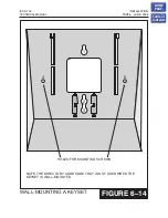
6.7B WALL-MOUNTING KEYSETS WITH ULTRA BASE
WEDGE
DCS keysets now come equipped with a new Ultra Base wedge. These base wedges
are reversible and can be used for wall-mounting however not every wall mounting
scenario is appropriate. First and foremost there is only one keyhole in the center of the
base attaching to the wall, and these base wedges can not be used with the standard
wall mount bracket with the two button/pins. To wall-mount the keyset using Ultra Base
wedges use screw holes 1, 2 and 3 to mount the base wedge on dry wall with the hole
in the middle for cable access
6.7C WALL-MOUNTING iDCS KEYSETS
The iDCS keysets come equipped with a reversible base wedge. To wall-mount a
keyset, remove the wedge from the keyset and mount the wedge to the wall using one
of the methods below
Use screw holes 1 and 2 to attach the base wedge to a standard electrical outlet box.
OR
Use screw holes 1 and 3 to attach to a standard telephone wall-mount plate with
locking pins. This method can cause the keyset to wobble as the keyset feet do not fit
securely to the mounting surface.
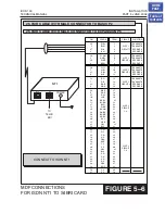
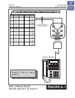
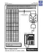
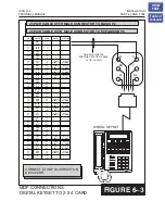
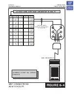
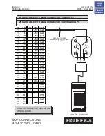
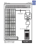
6.8 64 BUTTON MODULES
Using one pair twisted #24 AWG or #26 AWG jumper wire, cross-connect each 64
button module (64 BM) to the DLI port or plug into the DLI daughter board or your
choice
(see part 8 of the installation section)
. The 64 BM module can be assigned to
any keyset telephone. It must be assigned to that station in
four (4) 64 button modules can be programmed in the iDCS 100 system. A maximum of
two (2) 64 button modules per keyset.
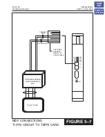
6.9 ATTACHING DCS 32 BUTTON AOM AND DCS 64
BUTTON MODULES TO MASTER STATION
These new Ultra Base Wedges allow a connector clip (packaged with 64B Modules and
AOMs) to be connected to the underside of the new style wedge and attach AOM(s) or
64B module(s) together with the main or “master” station. This “clip” allows multiple
64B modules and or AOMs to be secured or “chained” together to the main or “master”
station they are associated with. This will make instruments associated with each other
seem as one unit
(see Figure 6-17, 6-18 and 6-19)
HOME
PAGE
Table of
Contents


