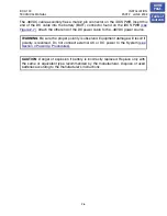
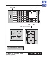
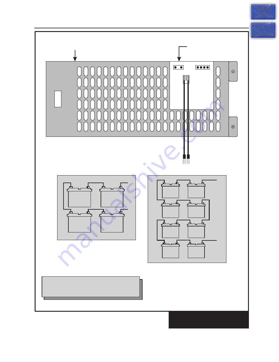
RESERVE POWER BATTERY
CONNECTIONS
FIGURE 2–7
iDCS 100
INSTALLATION
TECHNICAL MANUAL
PART 2 JUNE 2002
–
+
12V
–
+
12V
–
+
12V
–
+
12V
+
–
+
–
–
+
6V
–
+
6V
6V
6V
–
+
6V
–
+
6V
6V
6V
–
+
–
+
–
+
–
+
RESERVE POWER
BATTERY CONNECTOR
BLACK
RED
CONNECT TO EITHER A OR B
OPTION A
OPTION B
BATTERIES SHOULD BE PLACED
WITHIN THREE FEET OF KSU
POWER SUPPLY
HOME
PAGE
Table of
Contents