iDCS 100
INSTALLATION
TECHNICAL MANUAL
PART 3 JUNE 2002
3.4
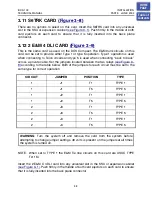
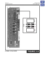
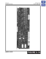
The S4BRI card is equipped with dip switch controlled line termination resistors. If a BRI
circuit is to be used as a Trunk circuit these switches must be in the OFF position. If a
circuit is to be used as a station then the dip switches for that circuit must be in the ON
position.
CIRCUIT DIP
SWITCH
1 SW
1
2 SW
2
3 SW
3
4 SW
4
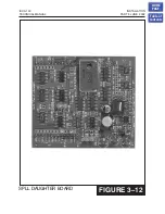
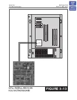
NOTE: In order for BRI circuits to operate the system must have an SPLL board
installed in the KSU.
3.14 iDCS TEPRI CARD
Removing the Cover
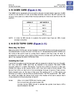
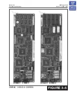
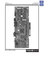
Before the iDCS TEPRI card can be installed in the iDCS 100 the card module must first
be disassembled to allow the card to fit the slot. To disassemble the iDCS TEPRI card,
first remove the ejector tabs by pulling them outward until they snap off. Next, to
separate the two halves of the casing, remove the four screws and pull the two halves
apart. This releases the iDCS TEPRI card PCB.
Installing the Card
The iDCS 100 system must be equipped with an expansion cabinet (Type-A or Type-B),
and only one iDCS TEPRI card may be installed in the system. The iDCS TEPRI
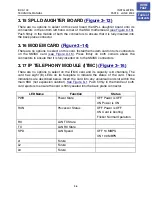
supports either T1 or ISDN PRI service. The first four LEDs on the front of the card
provide the status of the service (Sync, AIS, Loss and Layer 2 Active states). The
second four LED’s on the front of the card display the type of service. There are two
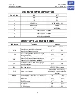
RJ45 modular jacks on the face of the card. The settings for T1 or PRI service are
selected by a bank of dip switches as defined below. The PRI supports NI1, NI2, AT&T
No. 5 ESS, and DMS 100 offices. Push firmly in the middle of the card to ensure that it
is fully inserted into the back plane connector.
Notes:
A Rev. 04 or later TEPRI card must be used.
Do not insert card with system power ON.
In order for the TEPRI circuits to operate the system must have a SPLL
board installed in the KSU.
HOME
PAGE
Table of
Contents

