


iDCS 100
INSTALLATION
TECHNICAL MANUAL
PART 6 JUNE 2002
6.1
PART 6. CONNECTING STATION EQUIPMENT
6.1 SAFETY PRECAUTIONS
To limit the risk of personal injury, always follow these precautions before connecting
telephone circuits:
a. Never install telephone wiring during a lightning storm.
b. Never install telephone jacks in a wet location unless the jack is specifically
designed for wet locations.
c. Never touch uninsulated telephone wires or terminals unless the telephone line has
been disconnected at the network interface.
d. Use caution when installing or modifying telephone lines.
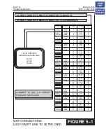
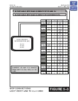
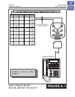
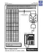
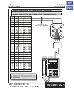
6.2 KEYSETS
Using one pair twisted #24 AWG or #26 AWG jumper wire, cross-connect each keyset
to the DLI port of your choice
(see Figures 6–1, 6–2, and 6-3)
NOTE: Because the iDCS 100 is a self-configuring system, if you connect a 12 button
keyset to a DLI port that previously had a 24 button keyset installed, the
existing data will be rewritten with 12 button keyset default data
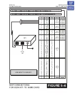
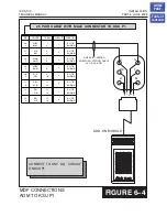
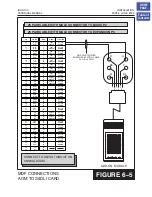
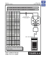
6.3 DCS 32 BUTTON ADD-ON MODULE
Using one pair twisted #24 AWG or #26 AWG jumper wire, cross-connect each add-on
module (AOM) to the DLI port of your choice
(see Figures 6–4, 6-5, and 6-6)
If an AOM is to operate as a stand-alone unit, there is nothing else required other than
assigning keys. When an AOM is to be used with a station, it must be assigned in
. Add-on modules can be assigned to any keyset.
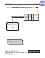
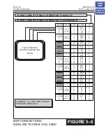
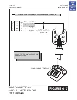
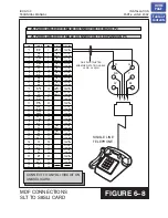
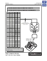
6.4 SINGLE LINE TELEPHONE
Using one pair twisted #24 AWG or #26 AWG jumper wire, cross-connect each single
line telephone to the SLI port of your choice
(see Figures 6–7, 6–8, and 6-9)
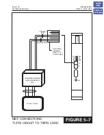
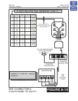
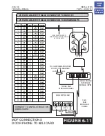
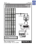
6.5 DOOR PHONE AND DOOR LOCK RELEASE
Using one pair twisted #24 AWG or #26 AWG jumper wire, cross-connect each DPIM
to the DLI port of your choice
(see Figures 6–10, 6-11, and 6–12)
DPIM to the door phone using #24 AWG or #26 AWG twisted pair wire.
HOME
PAGE
Table of
Contents


