OSCILLATOR CIRCUITS
KS57C2308/P2308/C2316/P2316
6-2
Clock Control Registers
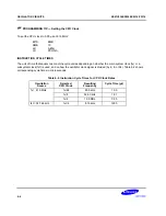
When the system clock mode control register, SCMOD, and the power control register, PCON, are both cleared
to zero after
RESET
, the normal CPU operating mode is enabled, a main system clock of fx/64 is selected, and
main system clock oscillation is initiated.
PCON is used to select normal CPU operating mode or one of two power-down modes — stop or idle. Bits 3 and
2 of the PCON register can be manipulated by a STOP or IDLE instruction to engage stop or idle power-down
mode.
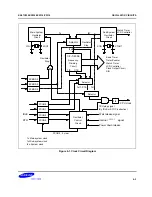
The system clock mode control register, SCMOD, lets you select the
main system clock (fx)
or a
subsystem clock
(fxt)
as the CPU clock and to start (or stop) main or sub system clock oscillation. The resulting clock source,
either main system clock or subsystem clock, is referred to as the
CPU clock.
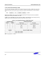
The main system clock is selected and oscillation started when all SCMOD bits are cleared to logic zero. By
setting SCMOD.3, SCMOD.2 and SCMOD.0 to different values, CPU can operate in a subsystem clock source
and start or stop main or sub system clock oscillation. To stop main system clock oscillation, you must use the
STOP instruction (assuming the main system clock is selected) or manipulate SCMOD.3 to “1” (assuming the
sub system clock is selected).
The main system clock frequencies can be divided by 4, 8, or 64 and a subsystem clock frequencies can only be
divided by 4. By manipulating PCON bits 1 and 0, you select one of the following frequencies as CPU clock.
fx/4, fxt/4, fx/8, fx/64
Using a Subsystem Clock
If a subsystem clock is being used as the selected system clock, the idle power-down mode can be initiated by
executing an IDLE instruction. The subsystem clock can be stopped by setting SCMOD.2 to “1”.
The watch timer, buzzer and LCD display operate normally with a subsystem clock source, since they operate at
very slow speeds (122 µs at 32.768 kHz) and with very low power consumption.
Summary of Contents for KS57C2308
Page 30: ...ADDRESS SPACES KS57C2308 P2308 C2316 P2316 2 22 NOTES ...
Page 168: ...SAM47 INSTRUCTION SET KS57C2308 P2308 C2316 P2316 5 94 NOTES ...
Page 170: ......
Page 206: ...POWER DOWN KS57C2308 P2308 C2316 P2316 8 8 NOTES ...
Page 210: ...RESET KS57C2308 P2308 C2316 P2316 9 4 NOTES ...
Page 222: ...I O PORTS KS57C2308 P2308 C2316 P2316 10 12 NOTES ...
Page 272: ...LCD CONTROLLER DRIVER KS57C2308 P2308 C2316 P2316 12 24 NOTES ...
Page 280: ...SERIAL I O INTERFACE KS57C2308 P2308 C2316 P2316 13 8 NOTES ...
Page 294: ...MECHANICAL DATA KS57C2308 P2308 C2316 P2316 15 2 NOTES ...
Page 310: ...KS57P2308 P2316 OTP KS57C2308 P2308 C2316 P2316 16 16 NOTES ...
Page 318: ......
Page 320: ......
Page 322: ......
Page 325: ......
Page 327: ......


