KS57C2308/P2308/C2316/P2316
OSCILLATOR CIRCUITS
6-7
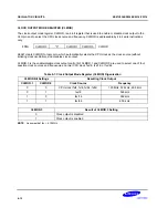
SYSTEM CLOCK MODE REGISTER (SCMOD)
The system clock mode register, SCMOD, is a 4-bit register that is used to select the CPU clock and to control
main and sub-system clock oscillation. SCMOD is mapped to the RAM address FB7H.
When main system clock is used as clock source, main system clock oscillation can be stopped by STOP
instruction or setting SCMOD.3 (not recommended).
When the clock source is subsystem clock, main system clock oscillation is stopped by setting SCMOD.3.
SCMOD.0, SCMOD2, and SCMOD.3 cannot be simultaneously modified. Sub-oscillation goes into stop mode
only by SCMOD.2. PCON which revokes stop mode cannot stop the sub-oscillation. The stop of sub-oscillation is
released only by reset.
RESET
clears all SCMOD values to logic zero, selecting the main system clock (fx) as the CPU clock and
starting clock oscillation. The reset value of the SCMOD is 0.
SCMOD.3, SCMOD.2, and SCMOD.0 bits can be manipulated by 1-bit write instructions (In other words,
SCMOD.0, SCMOD.2, and SCMOD.3 cannot be modified simultaneously by a 4-bit write). Bit 1 is always logic
zero.
FB7H
SCMOD.3
SCMOD.2
"0"
SCMOD.0
SCMOD
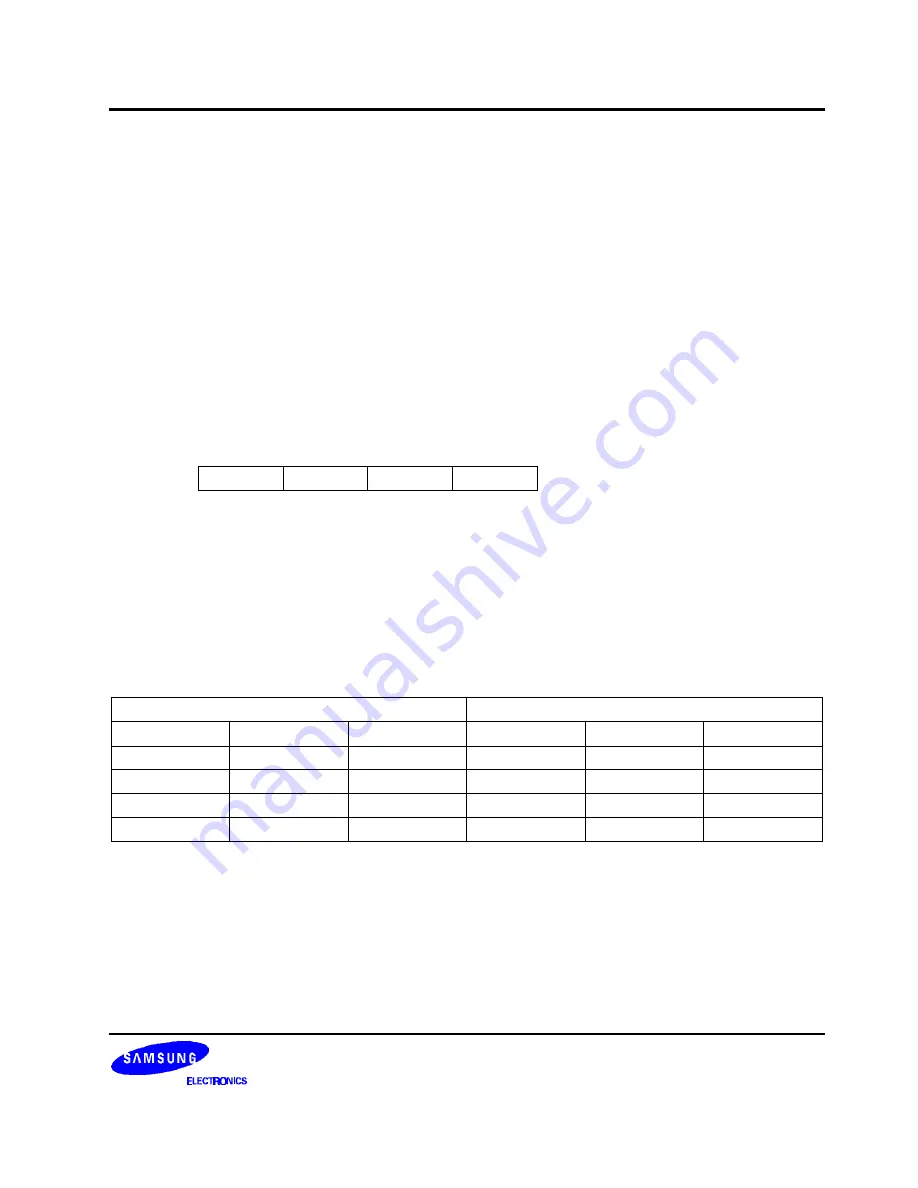
A subsystem clock (fxt) can be selected as the system clock by manipulating the SCMOD.3 and SCMOD.0 bit
settings. If SCMOD.3 = "0" and SCMOD.0 = "1", the subsystem clock is selected and main system clock
oscillation continues. If SCMOD.3 = "1" and SCMOD.0 = "1", fxt is selected, but main system clock oscillation
stops.
If you have selected fx as the CPU clock, setting SCMOD.3 to "1" will stop main system clock oscillation. But this
mode must not be used. To stop main system clock oscillation safely, main oscillation clock should be stopped
only by a STOP instruction in main system clock mode.
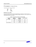
Table 6-3. System Clock Mode Register (SCMOD) Organization
SCMOD Register Bit Settings
Resulting Clock Selection
SCMOD.3
SCMOD.2
SCMOD.0
fx Oscillation
fxt Oscillation
CPU Clock
(note)
0
0
0
On
On
fx
0
1
0
On
Off
fx
0
0
1
On
On
fxt
1
0
1
Off
On
fxt
NOTE:
CPU clock is selected by PCON register settings.
Summary of Contents for KS57C2308
Page 30: ...ADDRESS SPACES KS57C2308 P2308 C2316 P2316 2 22 NOTES ...
Page 168: ...SAM47 INSTRUCTION SET KS57C2308 P2308 C2316 P2316 5 94 NOTES ...
Page 170: ......
Page 206: ...POWER DOWN KS57C2308 P2308 C2316 P2316 8 8 NOTES ...
Page 210: ...RESET KS57C2308 P2308 C2316 P2316 9 4 NOTES ...
Page 222: ...I O PORTS KS57C2308 P2308 C2316 P2316 10 12 NOTES ...
Page 272: ...LCD CONTROLLER DRIVER KS57C2308 P2308 C2316 P2316 12 24 NOTES ...
Page 280: ...SERIAL I O INTERFACE KS57C2308 P2308 C2316 P2316 13 8 NOTES ...
Page 294: ...MECHANICAL DATA KS57C2308 P2308 C2316 P2316 15 2 NOTES ...
Page 310: ...KS57P2308 P2316 OTP KS57C2308 P2308 C2316 P2316 16 16 NOTES ...
Page 318: ......
Page 320: ......
Page 322: ......
Page 325: ......
Page 327: ......


