KS57C2308/P2308/C2316/P2316
OSCILLATOR CIRCUITS
6-11
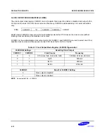
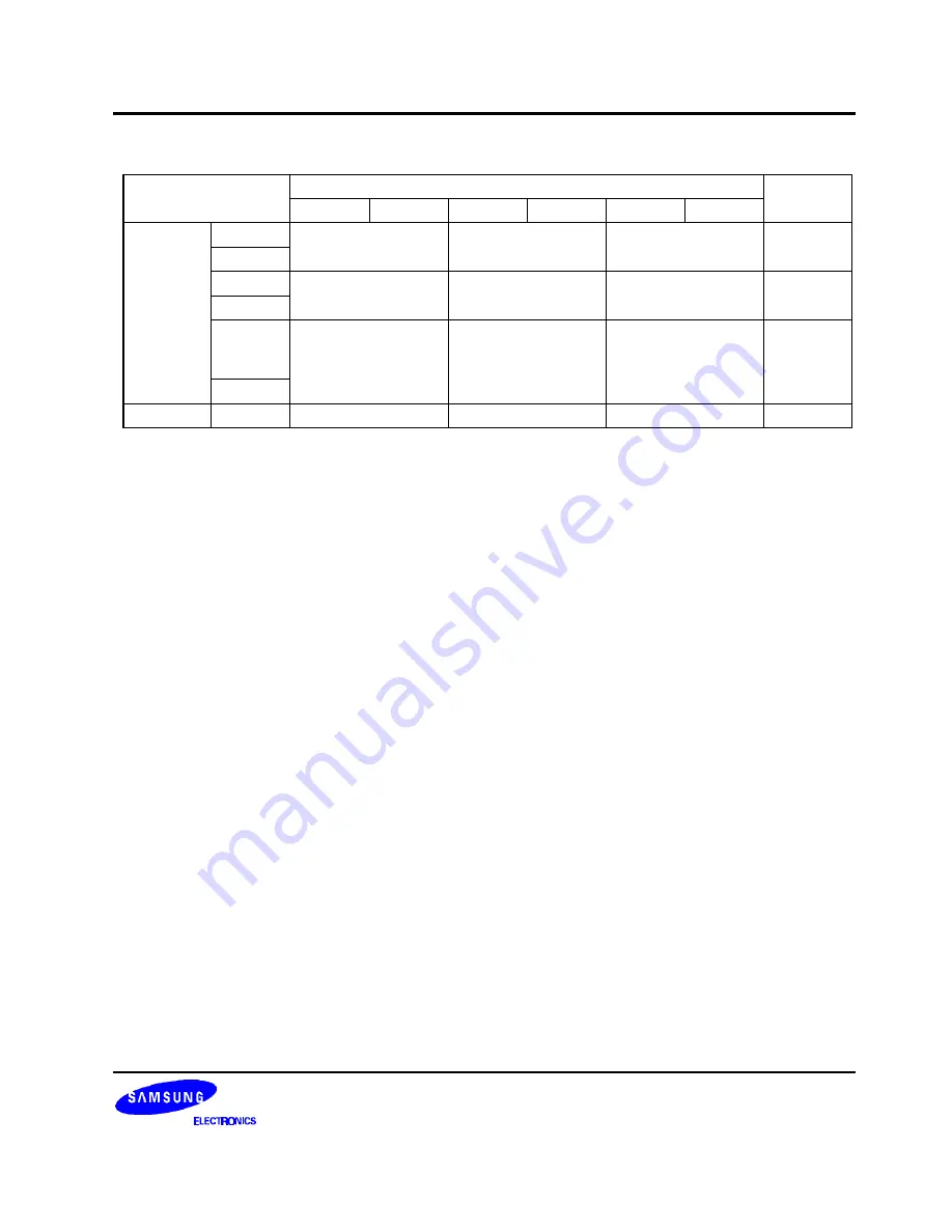
Table 6-6. Elapsed Machine Cycles During CPU Clock Switch
AFTER
SCMOD.0 = 0
SCMOD.0 = 1
BEFORE
PCON.1 = 0 PCON.0 = 0 PCON.1 = 1 PCON.0 = 0 PCON.1 = 1 PCON.0 = 1
PCON.1 = 0
N/A
1 MACHINE CYCLE
1 MACHINE CYCLE
PCON.0 = 0
SCMOD.0 = 0 PCON.1 = 1
8 MACHINE CYCLES
N/A
8 MACHINE CYCLES
N/A
PCON.0 = 0
PCON.1 = 1
16 MACHINE CYCLES
16 MACHINE CYCLES
N/A
fx/4fxt
MACHINE
CYCLE
PCON.0 = 1
SCMOD.0 = 1
N/A
N/A
fx/4fxt (M/C)
N/A
NOTES
:
1.
Even if oscillation is stopped by setting SCMOD.3 during main system clock operation, the stop mode is not entered.
2.
Since the X
IN
input is connected internally to V
SS
to avoid current leakage due to the crystal oscillator in stop mode, do
not set SCMOD.3 to "1" or STOP instruction when an external clock is used as the main system clock.
3.
When the system clock is switched to the subsystem clock, it is necessary to disable any interrupts which may occur
during the time intervals shown in Table 6-6.
4.
“N/A” means “not available”.
5.
fx: Main–system clock, fxt: Sub–system clock, M/C: Machine Cycle.
When fx is 4.19 MHz, and fxt is 32.768 kHz.
+
+
PROGRAMMING TIP — Switching Between Main System and Subsystem Clock
1. Switch from the main system clock to the subsystem clock:
MA2SUB BITS
SCMOD.0
; Switches to subsystem clock
CALL
DLY80
; Delay 80 machine cycles
BITS
SCMOD.3
; Stop the main system clock
RET
DLY80
LD
A,#0FH
DEL1
NOP
NOP
DECS
A
JR
DEL1
RET
2. Switch from the subsystem clock to the main system clock:
SUB2MA BITR
SCMOD.3
; Start main system clock oscillation
CALL
DLY80
; Delay 80 machine cycles
CALL
DLY80
; Delay 80 machine cycles
BITR
SCMOD.0
; Switch to main system clock
RET
Summary of Contents for KS57C2308
Page 30: ...ADDRESS SPACES KS57C2308 P2308 C2316 P2316 2 22 NOTES ...
Page 168: ...SAM47 INSTRUCTION SET KS57C2308 P2308 C2316 P2316 5 94 NOTES ...
Page 170: ......
Page 206: ...POWER DOWN KS57C2308 P2308 C2316 P2316 8 8 NOTES ...
Page 210: ...RESET KS57C2308 P2308 C2316 P2316 9 4 NOTES ...
Page 222: ...I O PORTS KS57C2308 P2308 C2316 P2316 10 12 NOTES ...
Page 272: ...LCD CONTROLLER DRIVER KS57C2308 P2308 C2316 P2316 12 24 NOTES ...
Page 280: ...SERIAL I O INTERFACE KS57C2308 P2308 C2316 P2316 13 8 NOTES ...
Page 294: ...MECHANICAL DATA KS57C2308 P2308 C2316 P2316 15 2 NOTES ...
Page 310: ...KS57P2308 P2316 OTP KS57C2308 P2308 C2316 P2316 16 16 NOTES ...
Page 318: ......
Page 320: ......
Page 322: ......
Page 325: ......
Page 327: ......


