KS57C2308/P2308/C2316/P2316
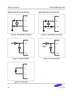
OSCILLATOR CIRCUITS
6-13
CLOCK OUTPUT CIRCUIT
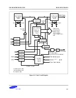
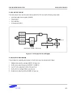
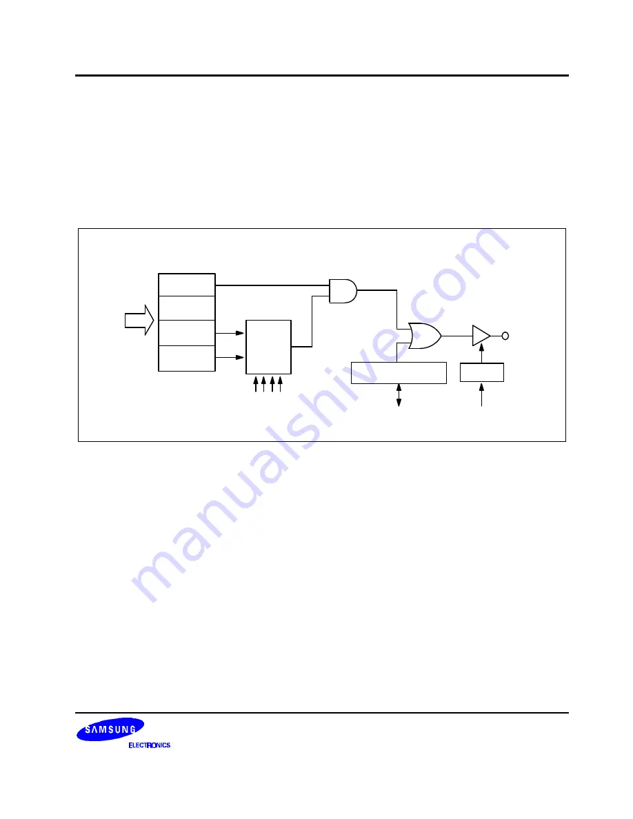
The clock output circuit, used to output clock pulses to the CLO pin, has the following components:
— 4-bit clock output mode register (CLMOD)
— Clock selector
— Port mode flag
— CLO output pin (P2.2)
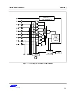
CLO
clocks
(fxx/8, fxx/16, fxx/64, CPU clock)
4
Clock
Selector
CLMOD.3
CLMOD.2
CLMOD.1
CLMOD.0
P2.2 OUTPUT LATCH
PM 2
Figure 6-7. CLO Output Pin Circuit Diagram
CLOCK OUTPUT PROCEDURE
The procedure for outputting clock pulses to the CLO pin may be summarized as follows:
1.
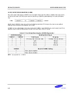
Disable clock output by clearing CLMOD.3 to logic zero.
2.
Set the clock output frequency (CLMOD.1, CLMOD.0).
3.
Load "0" to the output latch of the CLO pin (P2.2).
4.
Set the P2.2 mode flag (PM2) to output mode.
5.
Enable clock output by setting CLMOD.3 to logic one.
Summary of Contents for KS57C2308
Page 30: ...ADDRESS SPACES KS57C2308 P2308 C2316 P2316 2 22 NOTES ...
Page 168: ...SAM47 INSTRUCTION SET KS57C2308 P2308 C2316 P2316 5 94 NOTES ...
Page 170: ......
Page 206: ...POWER DOWN KS57C2308 P2308 C2316 P2316 8 8 NOTES ...
Page 210: ...RESET KS57C2308 P2308 C2316 P2316 9 4 NOTES ...
Page 222: ...I O PORTS KS57C2308 P2308 C2316 P2316 10 12 NOTES ...
Page 272: ...LCD CONTROLLER DRIVER KS57C2308 P2308 C2316 P2316 12 24 NOTES ...
Page 280: ...SERIAL I O INTERFACE KS57C2308 P2308 C2316 P2316 13 8 NOTES ...
Page 294: ...MECHANICAL DATA KS57C2308 P2308 C2316 P2316 15 2 NOTES ...
Page 310: ...KS57P2308 P2316 OTP KS57C2308 P2308 C2316 P2316 16 16 NOTES ...
Page 318: ......
Page 320: ......
Page 322: ......
Page 325: ......
Page 327: ......


