KS57C2308/P2308/C2316/P2316
INTERRUPTS
7-13
Interrupt Request Flags (IRQx)
Interrupt request flags are read/write addressable by 1-bit or 4-bit instructions. IRQx flags can be addressed
directly at their specific RAM addresses, regardless of the current value of the enable memory bank (EMB) flag.
When a specific IRQx flag is set to logic one, the corresponding interrupt request is generated. The flag is then
automatically cleared to logic zero when the interrupt has been serviced. Exceptions are the watch timer interrupt
request flags, IRQW, and the external interrupt 2 flag IRQ2, which must be cleared by software after the interrupt
service routine has executed. IRQx flags are also used to execute interrupt requests from software. In summary,
follow these guidelines for using IRQx flags:
1.
IRQx is set to request an interrupt when an interrupt meets the set condition for interrupt generation.
2.
IRQx is set to "1" by hardware and then cleared by hardware when the interrupt has been serviced (with the
exception of IRQW and IRQ2).
3.
When IRQx is set to "1" by software, an interrupt is generated.
When two interrupts share the same service routine start address, interrupt processing may occur in one of two
ways:
— When only one interrupt is enabled, the IRQx flag is cleared automatically when the interrupt has been
serviced.
— When two interrupts are enabled, the request flag is not automatically cleared so that the user has an
opportunity to locate the source of the interrupt request. In this case, the IRQx setting must be cleared
manually using a BTSTZ instruction.
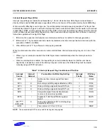
Table 7-8. Interrupt Request Flag Conditions and Priorities
Interrupt
Source
Internal /
External
Pre-condition for IRQx Flag Setting
Interrupt
Priority
IRQ Flag
Name
INTB
I
Reference time interval signal from basic
timer
1
IRQB
INT4
E
Both rising and falling edges detected at INT4
1
IRQ4
INT0
E
Rising or falling edge detected at INT0 pin
2
IRQ0
INT1
E
Rising or falling edge detected at INT1 pin
3
IRQ1
INTS
I
Completion signal for serial transmit-and-
receive or receive-only operation
4
IRQS
INTT0
I
Signals for TCNT0 and TREF0 registers
match
5
IRQT0
INT2
(note)
(KS0–KS7)
E
Rising edge detected at INT2 or falling edge
detected at KS0–KS7
–
IRQ2
INTW
I
Time interval of 0.5 s or 3.19 ms
–
IRQW
NOTE
: The quasi-interrupt INT2 is only used for testing incoming signals.
Summary of Contents for KS57C2308
Page 30: ...ADDRESS SPACES KS57C2308 P2308 C2316 P2316 2 22 NOTES ...
Page 168: ...SAM47 INSTRUCTION SET KS57C2308 P2308 C2316 P2316 5 94 NOTES ...
Page 170: ......
Page 206: ...POWER DOWN KS57C2308 P2308 C2316 P2316 8 8 NOTES ...
Page 210: ...RESET KS57C2308 P2308 C2316 P2316 9 4 NOTES ...
Page 222: ...I O PORTS KS57C2308 P2308 C2316 P2316 10 12 NOTES ...
Page 272: ...LCD CONTROLLER DRIVER KS57C2308 P2308 C2316 P2316 12 24 NOTES ...
Page 280: ...SERIAL I O INTERFACE KS57C2308 P2308 C2316 P2316 13 8 NOTES ...
Page 294: ...MECHANICAL DATA KS57C2308 P2308 C2316 P2316 15 2 NOTES ...
Page 310: ...KS57P2308 P2316 OTP KS57C2308 P2308 C2316 P2316 16 16 NOTES ...
Page 318: ......
Page 320: ......
Page 322: ......
Page 325: ......
Page 327: ......

