POWER-DOWN
KS57C2308/P2308/C2316/P2316
8-6
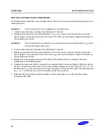
PORT PIN CONFIGURATION FOR POWER-DOWN
The following method describes how to configure I/O port pins to reduce power consumption during power-down
modes (stop, idle):
Condition 1:
If the microcontroller is not configured to an external device:
1.
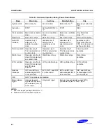
Connect unused port pins according to the information in Table 8-2.
2.
Disable pull-up resistors for input pins configured to V
DD
or V
SS
levels in order to check the current input
option. Reason: If the input level of a port pin is set to V
SS
when a pull-up resistor is enabled, it will draw an
unnecessarily large current.
Condition 2:
If the microcontroller is configured to an external device and the external device's V
DD
source
is turned off in power-down mode.
1.
Connect unused port pins according to the information in Table 8-2.
2.
Disable pull-up resistors for input pins configured to V
DD
or V
SS
levels in order to check the current input
option. Reason: If the input level of a port pin is set to V
SS
when a pull-up resistor is enabled, it will draw an
unnecessarily large current.
3.
Disable the pull-up resistors of input pins connected to the external device by making the necessary
modifications to the PUMOD register.
4.
Configure the output pins that are connected to the external device to low level. Reason: When the external
device's V
DD
source is turned off, and if the microcontroller's output pins are set to high level, V
DD
– 0.7 V is
supplied to the V
DD
of the external device through its input pin. This causes the device to operate at the level
V
DD
– 0.7 V. In this case, total current consumption would not be reduced.
5.
Determine the correct output pin state necessary to block current pass in according with the external
transistors (PNP, NPN).
Summary of Contents for KS57C2308
Page 30: ...ADDRESS SPACES KS57C2308 P2308 C2316 P2316 2 22 NOTES ...
Page 168: ...SAM47 INSTRUCTION SET KS57C2308 P2308 C2316 P2316 5 94 NOTES ...
Page 170: ......
Page 206: ...POWER DOWN KS57C2308 P2308 C2316 P2316 8 8 NOTES ...
Page 210: ...RESET KS57C2308 P2308 C2316 P2316 9 4 NOTES ...
Page 222: ...I O PORTS KS57C2308 P2308 C2316 P2316 10 12 NOTES ...
Page 272: ...LCD CONTROLLER DRIVER KS57C2308 P2308 C2316 P2316 12 24 NOTES ...
Page 280: ...SERIAL I O INTERFACE KS57C2308 P2308 C2316 P2316 13 8 NOTES ...
Page 294: ...MECHANICAL DATA KS57C2308 P2308 C2316 P2316 15 2 NOTES ...
Page 310: ...KS57P2308 P2316 OTP KS57C2308 P2308 C2316 P2316 16 16 NOTES ...
Page 318: ......
Page 320: ......
Page 322: ......
Page 325: ......
Page 327: ......


