TIMERS and TIMER/COUNTERS
KS57C2308/P2308/C2316/P2316
11-20
TC0 REFERENCE REGISTER (TREF0)
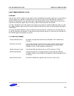
The TC0 reference register TREF0 is an 8-bit write-only register. It is addressable by 8-bit RAM control
instructions.
RESET
initializes the TREF0 value to “FFH”.
TREF0 is used to store a reference value to be compared to the incrementing TCNT0 register in order to identify
an elapsed time interval. Reference values will differ depending upon the specific function that TC0 is being used
to perform — as a programmable timer/counter, event counter, clock signal divider, or arbitrary frequency output
source.
During timer/counter operation, the value loaded into the reference register is compared to the TCNT0 value.
When TCNT0 = TREF0, the TC0 output latch (TOL0) is inverted and an interrupt request is generated to signal
the interval or event. The TREF0 value, together with the TMOD0 clock frequency selection, determines the
specific TC0 timer interval. Use the following formula to calculate the correct value to load to the TREF0
reference register:
TC0 timer interval = (TREF0 value + 1)
×
1
TMOD0 frequency setting
(TREF0 value
≠
0)
TC0 OUTPUT ENABLE FLAG (TOE0)
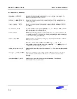
The 1-bit timer/counter 0 output enable flag TOE0 controls output from timer/counter 0 to the TCLO0 pin. TOE0
is addressable by 1-bit write instructions.
(MSB)
(LSB)
F92H
“U”
TOE0
"U"
"U"
NOTE
: “U” indicates unknown state.
When you set the TOE0 flag to "1", the contents of TOL0 can be output to the TCLO0 pin. Whenever a
RESET
occurs, TOE0 is automatically set to logic zero, disabling all TC0 output. Even when the TOE0 flag is disabled,
timer/counter 0 can continue to output an internally-generated clock frequency, via TOL0, to the serial I/O clock
selector circuit.
TC0 OUTPUT LATCH (TOL0)
TOL0 is the output latch for timer/counter 0. When the 8-bit comparator detects a correspondence between the
value of the counter register TCNT0 and the reference value stored in the TREF0 register, the TOL0 value is
inverted — the latch toggles high-to-low or low-to-high. Whenever the state of TOL0 is switched, the TC0 signal
is output. TC0 output may be directed to the TCLO0 pin, or it can be output directly to the serial I/O clock
selector circuit as the
SCK
signal.
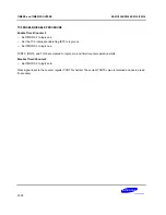
Assuming TC0 is enabled, when bit 3 of the TMOD0 register is set to "1", the TOL0 latch is cleared to logic zero,
along with the counter register TCNT0 and the interrupt request flag, IRQT0, and counting resumes immediately.
When TC0 is disabled (TMOD0.2 = "0"), the contents of the TOL0 latch are retained and can be read, if
necessary.
Summary of Contents for KS57C2308
Page 30: ...ADDRESS SPACES KS57C2308 P2308 C2316 P2316 2 22 NOTES ...
Page 168: ...SAM47 INSTRUCTION SET KS57C2308 P2308 C2316 P2316 5 94 NOTES ...
Page 170: ......
Page 206: ...POWER DOWN KS57C2308 P2308 C2316 P2316 8 8 NOTES ...
Page 210: ...RESET KS57C2308 P2308 C2316 P2316 9 4 NOTES ...
Page 222: ...I O PORTS KS57C2308 P2308 C2316 P2316 10 12 NOTES ...
Page 272: ...LCD CONTROLLER DRIVER KS57C2308 P2308 C2316 P2316 12 24 NOTES ...
Page 280: ...SERIAL I O INTERFACE KS57C2308 P2308 C2316 P2316 13 8 NOTES ...
Page 294: ...MECHANICAL DATA KS57C2308 P2308 C2316 P2316 15 2 NOTES ...
Page 310: ...KS57P2308 P2316 OTP KS57C2308 P2308 C2316 P2316 16 16 NOTES ...
Page 318: ......
Page 320: ......
Page 322: ......
Page 325: ......
Page 327: ......

