LCD CONTROLLER/DRIVER
KS57C2308/P2308/C2316/P2316
12-8
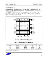
COMMON (COM) SIGNALS
The common signal output pin selection (COM pin selection) varies according to the selected duty cycle. You
must therefore be open any unused COM pins according to this guideline:
— In static mode, be open the COM1, COM2, and COM3 pins
— In 1/2 duty mode, be open the COM2 and COM3 pin
— In 1/3 duty mode, be open the COM3 pin
Table 12-6. Common Signal Pins Used Per Duty Cycle
Display Mode
COM0 Pin
COM1 Pin
COM2 Pin
COM3 Pin
Static
Selected
N/C
N/C
N/C
1/2 duty
Selected
Selected
N/C
N/C
1/3 duty
Selected
Selected
Selected
N/C
1/4 duty
Selected
Selected
Selected
Selected
NOTE
: “NC” means that no connection is required.
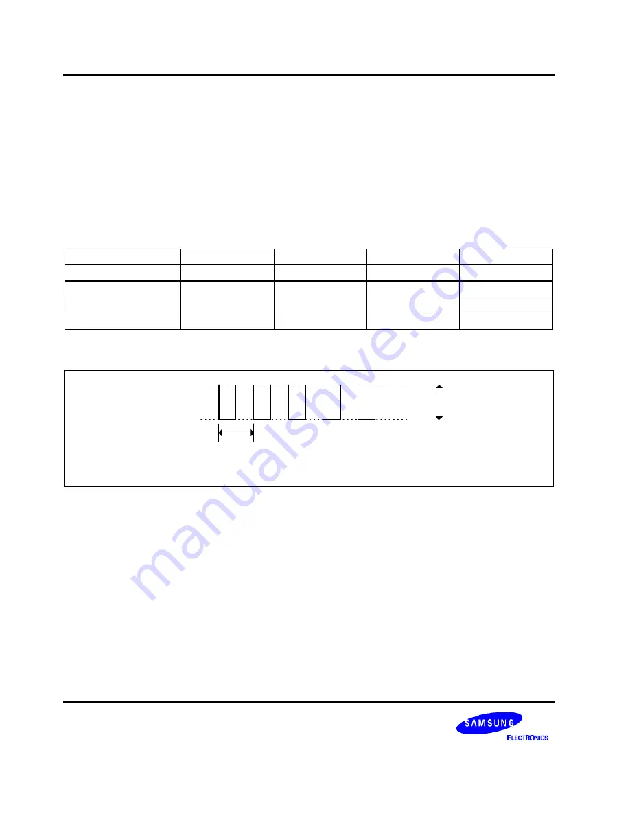
V
LCD
T
f
= T
COM0
V
LC0
V
SS
T: LCDCK
T
f
: Frame frequency
Figure 12-5. LCD Common Signal Waveform (Static)
Summary of Contents for KS57C2308
Page 30: ...ADDRESS SPACES KS57C2308 P2308 C2316 P2316 2 22 NOTES ...
Page 168: ...SAM47 INSTRUCTION SET KS57C2308 P2308 C2316 P2316 5 94 NOTES ...
Page 170: ......
Page 206: ...POWER DOWN KS57C2308 P2308 C2316 P2316 8 8 NOTES ...
Page 210: ...RESET KS57C2308 P2308 C2316 P2316 9 4 NOTES ...
Page 222: ...I O PORTS KS57C2308 P2308 C2316 P2316 10 12 NOTES ...
Page 272: ...LCD CONTROLLER DRIVER KS57C2308 P2308 C2316 P2316 12 24 NOTES ...
Page 280: ...SERIAL I O INTERFACE KS57C2308 P2308 C2316 P2316 13 8 NOTES ...
Page 294: ...MECHANICAL DATA KS57C2308 P2308 C2316 P2316 15 2 NOTES ...
Page 310: ...KS57P2308 P2316 OTP KS57C2308 P2308 C2316 P2316 16 16 NOTES ...
Page 318: ......
Page 320: ......
Page 322: ......
Page 325: ......
Page 327: ......


