MEMORY MAP
KS57C2308/P2308/C2316/P2316
4-18
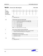
LCON
— LCD Output Control Register
F8EH
Bit
3
2
1
0
Identifier
"0"
.2
"0"
.0
RESET
Value
0
0
0
0
Read/Write
W
W
W
W
Bit Addressing
4
4
4
4
.3
LCD Bias Selection Bit
0
This bit is used for internal testing only; always logic zero.
.2
LCD Clock Output Disable/Enable Bit
0
Disable LCDCK and LCDSY signal outputs.
1
Enable LCDCK and LCDSY signal outputs.
.1
Bit 1
0
Always logic zero
.0
LCD Display Control Bit
0
LCD output low, turns display off: cut off current to dividing resistor, and output
port 8 latch contents.
1
If LMOD.3 = “0”, turns display off; output port 8 latch contents;
If LMOD.3 = “1”, COM and SEG output in display mode; LCD display on.
NOTES:
1.
You can manipulate LCON.0, when you try to turn ON/OFF LCD display internally. If you want to control LCD
ON/OFF or LCD contrast externally, you should set the LCON.0 to "0". refer to chapter 12, if you need more
information.
2.
To select the LCD bias, you must properly configure both LMOD register and the external LCD bias circuit
connection.
Summary of Contents for KS57C2308
Page 30: ...ADDRESS SPACES KS57C2308 P2308 C2316 P2316 2 22 NOTES ...
Page 168: ...SAM47 INSTRUCTION SET KS57C2308 P2308 C2316 P2316 5 94 NOTES ...
Page 170: ......
Page 206: ...POWER DOWN KS57C2308 P2308 C2316 P2316 8 8 NOTES ...
Page 210: ...RESET KS57C2308 P2308 C2316 P2316 9 4 NOTES ...
Page 222: ...I O PORTS KS57C2308 P2308 C2316 P2316 10 12 NOTES ...
Page 272: ...LCD CONTROLLER DRIVER KS57C2308 P2308 C2316 P2316 12 24 NOTES ...
Page 280: ...SERIAL I O INTERFACE KS57C2308 P2308 C2316 P2316 13 8 NOTES ...
Page 294: ...MECHANICAL DATA KS57C2308 P2308 C2316 P2316 15 2 NOTES ...
Page 310: ...KS57P2308 P2316 OTP KS57C2308 P2308 C2316 P2316 16 16 NOTES ...
Page 318: ......
Page 320: ......
Page 322: ......
Page 325: ......
Page 327: ......


