KS57C2308/P2308/C2316/P2316
MEMORY MAP
4-19
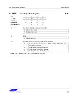
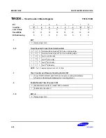
LMOD
— LCD Mode Register
F8DH, F8CH
Bit
7
6
5
4
3
2
1
0
Identifier
.7
.6
.5
.4
.3
.2
.1
.0
RESET
Value
0
0
0
0
0
0
0
0
Read/Write
W
W
W
W
W
W
W
W
Bit Addressing
8
8
8
8
1/8
8
8
8
.7–.6
LCD Output Segment and Pin Configuration Bits
0
0
Segments 24–27; and 28–31
0
1
Segment 24–27; 1-bit output at P8.4–P8.7
1
0
Segment 28–31; 1-bit output at P8.0–P8.3
1
1
1-bit output only at P8.0–P8.3, and P8.4–P8.7
.5–.4
LCD Clock (LCDCK) Frequency Selection Bits
0
0
fw/2
9
= 64 Hz
0
1
fw/2
8
= 128 Hz
1
0
fw/2
7
= 256 Hz
1
1
fw/2
6
= 512 Hz
NOTE
: Assuming watch timer clock (fw) = 32.768 kHz.
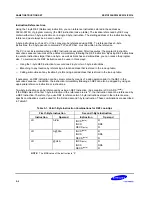
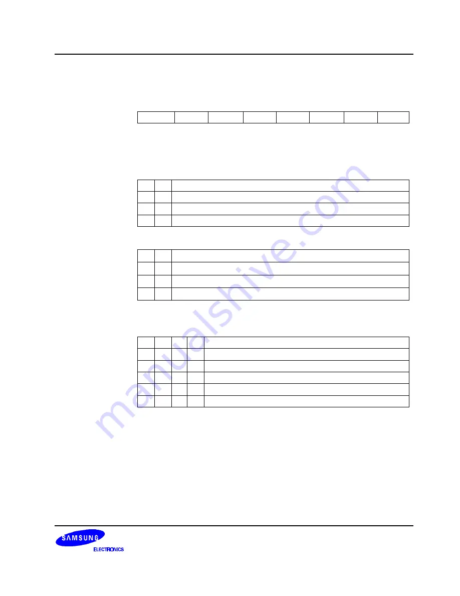
.3–.0
Duty and Bias Selection for LCD Display
0
–
–
–
LCD display off
1
0
0
0
1/4 duty, 1/3 bias
1
0
0
1
1/3 duty, 1/3 bias
1
0
1
0
1/2 duty, 1/2 bias
1
0
1
1
1/3 duty, 1/2 bias
1
1
0
0
Static
Summary of Contents for KS57C2308
Page 30: ...ADDRESS SPACES KS57C2308 P2308 C2316 P2316 2 22 NOTES ...
Page 168: ...SAM47 INSTRUCTION SET KS57C2308 P2308 C2316 P2316 5 94 NOTES ...
Page 170: ......
Page 206: ...POWER DOWN KS57C2308 P2308 C2316 P2316 8 8 NOTES ...
Page 210: ...RESET KS57C2308 P2308 C2316 P2316 9 4 NOTES ...
Page 222: ...I O PORTS KS57C2308 P2308 C2316 P2316 10 12 NOTES ...
Page 272: ...LCD CONTROLLER DRIVER KS57C2308 P2308 C2316 P2316 12 24 NOTES ...
Page 280: ...SERIAL I O INTERFACE KS57C2308 P2308 C2316 P2316 13 8 NOTES ...
Page 294: ...MECHANICAL DATA KS57C2308 P2308 C2316 P2316 15 2 NOTES ...
Page 310: ...KS57P2308 P2316 OTP KS57C2308 P2308 C2316 P2316 16 16 NOTES ...
Page 318: ......
Page 320: ......
Page 322: ......
Page 325: ......
Page 327: ......


