MEMORY MAP
KS57C2308/P2308/C2316/P2316
4-28
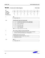
TMOD0
— Timer/Counter 0 Mode Register
F91H, F90H
Bit
7
6
5
4
3
2
1
0
Identifier
"0"
.6
.5
.4
.3
.2
"0"
"0"
RESET
Value
0
0
0
0
0
0
0
0
Read/Write
W
W
W
W
W
W
W
W
Bit Addressing
8
8
8
8
1/8
8
8
8
.7
Bit 7
0
Always logic zero
.6–.4
Timer/Counter 0 Input Clock Selection Bits
0
0
0
External clock input at TCL0 pin on rising edge
0
0
1
External clock input at TCL0 pin on falling edge
1
0
0
fxx/2
10
(4.09 kHz)
1
0
1
fxx/2
8
(16.4 kHz)
1
1
0
fxx/2
6
(65.5 kHz)
1
1
1
fxx/2
4
(262 kHz)
NOTE:
“fxx” = Selected system clock of 4.19 MHz
.3
Clear Counter and Resume Counting Control Bit
1
Clear TCNT0, IRQT0, and TOL0 and resume counting immediately
(This bit is cleared automatically when counting starts.)
.2
Enable/Disable Timer/Counter 0 Bit
0
Disable timer/counter 0; retain TCNT0 contents
1
Enable timer/counter 0
.1–.0
Bit 1–0
0
Always logic zero
Summary of Contents for KS57C2308
Page 30: ...ADDRESS SPACES KS57C2308 P2308 C2316 P2316 2 22 NOTES ...
Page 168: ...SAM47 INSTRUCTION SET KS57C2308 P2308 C2316 P2316 5 94 NOTES ...
Page 170: ......
Page 206: ...POWER DOWN KS57C2308 P2308 C2316 P2316 8 8 NOTES ...
Page 210: ...RESET KS57C2308 P2308 C2316 P2316 9 4 NOTES ...
Page 222: ...I O PORTS KS57C2308 P2308 C2316 P2316 10 12 NOTES ...
Page 272: ...LCD CONTROLLER DRIVER KS57C2308 P2308 C2316 P2316 12 24 NOTES ...
Page 280: ...SERIAL I O INTERFACE KS57C2308 P2308 C2316 P2316 13 8 NOTES ...
Page 294: ...MECHANICAL DATA KS57C2308 P2308 C2316 P2316 15 2 NOTES ...
Page 310: ...KS57P2308 P2316 OTP KS57C2308 P2308 C2316 P2316 16 16 NOTES ...
Page 318: ......
Page 320: ......
Page 322: ......
Page 325: ......
Page 327: ......


