


6-5
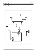
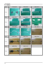
6. Wiring Diagram
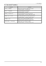
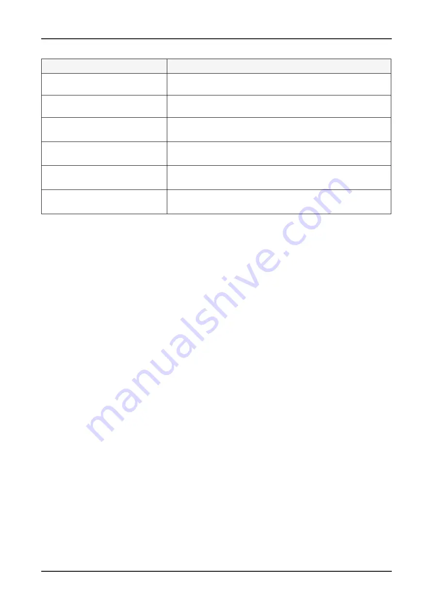
6-3. Connector Functions
Connector
Functions
CN1001 <-> CNM802
Supply dimming power from SMPS to Main Board.
* defective symptom : abnormal Picture
CN2101 <-> SPEAKER
Connection Main Board and Speaker.
* defective symptom : No picture
CN3002 <-> Function & IR
Connection Main Board and Function & IR Assy.
* defective symptom : No picture, diable Power On/Off
CN6001_FFC <-> T-CON
The LVDS signal transferred from Main Board to Panel.
* defective symptom : No picture but normal sound
CNM803 <-> CN1
Supply power and signal from SMPS to Inverter.
* defective symptom : No picture but normal sound
CN801S,GT801 <-> Inlet Socket
Supply power from Inlet Socket to SMPS.
* defective symptom : No picture but normal sound
Summary of Contents for LE26A451C1HX
Page 133: ...3 6 3 Disassembly and Reassemble Memo ...
Page 137: ...4 4 4 Troubleshooting WAVEFORMS 1 R G B Output Signal ...
Page 139: ...4 6 4 Troubleshooting WAVEFORMS 2 Digital Output Data 3 Signal of HDMI Data ...
Page 141: ...4 8 4 Troubleshooting WAVEFORMS 3 CVBS Output Signal 4 Tuner_CVBS Output Signal ...
Page 143: ...4 10 4 Troubleshooting WAVEFORMS 4 CVBS Output Signal ...
Page 145: ...4 12 4 Troubleshooting WAVEFORMS 2 Digital Output Data 5 Analog Signal Y C ...
Page 158: ...4 25 4 Troubleshooting 4 8 2 Software Upgrade Flash Downloader Flash Downloader ...
Page 163: ...6 4 6 Wiring Diagram 6 2 Wiring Picture ...
Page 169: ...1 4 1 Precautions Memo ...


