3 Alignments and Adjustments
3-14
8) YC Delay
NO
1
2
3
4
5
6
7
8
9
10
11
12
13
14
15
item
RF PAL-B/G
RF PAL-D/K
RF PAL- I
RF PAL- L/L'
RF SECAM-B/G
RF SECAM-D/K
RF SECAM-I
RF SECAM-L/L'
RF NTSC3.58
RF NTSC4.43
AV PAL
AV SECAM
AV NTSC 3.58
AV NTSC4.43
AV PAL60
TV/AV/S_Video
6
5
5
5
7
5
5
5
5
6
3
7
6
6
5
9. Adjust
NO
1
2
3
4
5
6
7
8
9
10
11
12
13
14
15
16
item
TTX PWM
Dyn. Contrast
Dyn. Brightness
Dyn. Color
Dyn. Sharpness
Std. Contrast
Std. Brightness
Std. Color
Std. Sharpness
Melody Volume
Brightness Center
Contrast Gain
MTK_Dyn.Contrast
DSP Recovery
Channel Table
Video Mute Time
value
30
100
45
55
75
80
50
55
50
20
38
64
On
Off
Suwon
10
1) User Control Initial
Summary of Contents for LE26S81BHX
Page 3: ...Contents...
Page 4: ...Contents...
Page 9: ...Memo 1 Precautions 1 4...
Page 11: ...2 Product Specifications 2 2 Item Description 2 2 LE26S81BH Specifications...
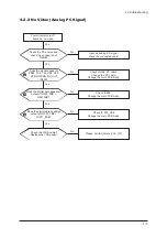
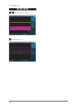
Page 41: ...4 Troubleshooting 4 4 WAVEFORMS 1 2 PC Input V Sync H Sync 3 LVDS Out CLK...
Page 43: ...4 Troubleshooting 4 6 4 5 HDMI Input CLK WAVEFORMS...
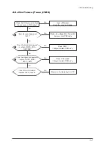
Page 45: ...4 Troubleshooting 4 8 WAVEFORMS 6 Tuner CVBS Out Pattern Grey Bar...
Page 47: ...4 Troubleshooting 4 10 WAVEFORMS 7 TS DATA Out CLK DATA 0 8 Eagle Out CLK H Sync...
Page 50: ...4 Troubleshooting 4 13 WAVEFORMS 9 S VIDEO Input Y C...
Page 52: ...4 Troubleshooting 4 15 WAVEFORMS 10 Component Input Y Pb...
Page 55: ...4 Troubleshooting 4 18 Memo...
Page 89: ...7 Block Diagrams 7 2 Memo...
Page 95: ...8 Wiring Diagrams 8 6 8 4 Power Board Layout...
Page 98: ...8 9 8 Wiring Diagrams...
Page 99: ...8 Wiring Diagrams 8 10...
Page 100: ...8 11 8 Wiring Diagrams...
Page 101: ...8 Wiring Diagrams 8 12 Memo...
Page 113: ...Memo 9 Schematic Diagrams 9 12...
Page 119: ...Memo 10 Operating Instructions and Installation 10 6...
Page 125: ...11 Disassembly and Reassembly 11 6 Memo...
Page 126: ...12 PCB Diagram 12 1 12 PCB Diagram 12 1 26 32 37 40 46 Main PCB Diagram...
Page 127: ...12 PCB Diagram 12 2 12 2 26 32 37 40 46 Main PCB Diagram...
Page 128: ...12 PCB Diagram 12 3 12 3 26 32 37 40 46 Main PCB Diagram CIS...
Page 129: ...12 PCB Diagram 12 4 12 4 26 32 SMPS...
Page 130: ...12 PCB Diagram 12 5 12 5 32 SMPS VE...
Page 131: ...12 PCB Diagram 12 6 12 6 37 SMPS...
Page 132: ...12 PCB Diagram 12 7 12 7 40 SMPS...
Page 133: ...12 PCB Diagram 12 8 12 8 46 SMPS...
Page 134: ...12 PCB Diagram 12 9 12 9 DIMMING BOARD...
Page 135: ...12 PCB Diagram 12 10 Memo...
Page 138: ...13 Circuit Descriptions 13 3 13 2 Main Block...
Page 143: ...13 Circuit Descriptions 13 8 Memo...
Page 159: ...Memo 14 Reference Infomation 14 16...


