background image


LCD TV 

Tanzanite

TRAINING MANUAL

Summary of Contents for LE32A Series

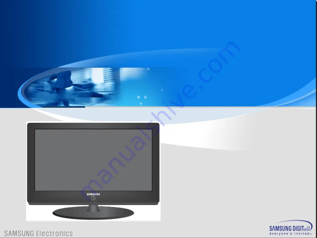
Page 1: ...LCD TV Tanzanite TRAINING MANUAL ...

Page 2: ...Agenda Agenda I Understanding of LCD TV II Inside of Tanzanite Model III Board description IV Disassembly V Trouble Shooting VI How to Upgrade VII Attachment ...

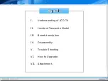
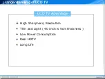
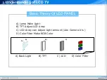
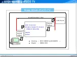
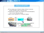
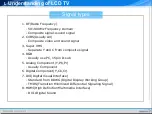
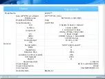
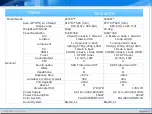
Page 3: ...Ⅰ Understanding of LCD TV UNDERSTANDING OF LCD TV ...

Page 4: ... Understanding of LCD TV CONTENTS CONTENTS I LCD TV advantage II Basic theory of LCD PANEL III Basic block of LCD TV IV Basic block of main PBA V What is scaler VI TV signal types VII TV connector types ...

Page 5: ...LCD TV Advantage Ⅰ Understanding of LCD TV High Sharpness Resolution Thin and Light 40 Inch is 5cm thickness Low Power Consumption Real HDTV Long Life ...

Page 6: ...y Of LCD PANEL Ⅰ Understanding of LCD TV A B C D A Back Light B TFT C LCD D Color Filter A Lamp Make Light B TFT Adjust LCD Array C LCD Array can Adjust Light amount Like Camera Iris D Color Filter Make RGB Color ...

Page 7: ...ock of LCD TV Ⅰ Understanding of LCD TV Analog Digital Signal Digital Signal Developement Part A D Converter Graphic Signal Processor IMAGE SCALER SMPS Audio LCD Panel Analog RF VIDEO S_VIDEO PC Digtal HDMI DVI ...

Page 8: ...rstanding of LCD TV B l ock D i agram PC P O W E R LC D P A N EL 5V 12V A D C I M A G E S C A LE R M i com A nal og P ar t D i gi t al P ar t R F VI D E O S VI D EO SC AR T 3 3V LV D S I nvert er Audi o Speaker A D C Vi deo D ecoder ...

Page 9: ...RT can display any resolution picture without conversion but LCD and PDP can do only with scaler Accepting input images from multiple sources and displaying them on any flat panel display Scaler is most important IC in flat panel display Scaler ...

Page 10: ...m composite signal 4 RGB Usually use PC 15pin D sub 5 Analog Component Y Pb Pr Usually Component 6 Digital Component Y Cb Cr 7 DVI Digital Visual Interface Standard from DDWG Digital Display Working Group TMDS Transition Minimized Differential Signaling Signal 8 HDMI High Definition Multimedia Interface DVI Digital Sound Signal types Ⅰ Understanding of LCD TV ...

Page 11: ...TV signal connector types Ⅰ Understanding of LCD TV Composite S Video Component HDMI HDMI Cable ...

Page 12: ...Ⅱ Inside of Tanzanite Model Inside of Tanzanite Model ...

Page 13: ...CONTENTS CONTENTS I Introduction II General specification III Control Connection Panel IV Block Diagram V Inner Features VI Some functions of Sonoma VII Key Parts Explanation Ⅱ Inside of Tanzanite Model ...

Page 14: ...Introduction Introduction Best Picture Quality Simple Function New Design Acceptable Price Support HDMI Some Functions Ⅱ Inside of Tanzanite Model ...

Page 15: ... component 1 component in back 480i p 576i p 720p 1080i PC 1 Dsub in back HDMI 2 HDMI in back 1 Side HDMI Tuner 1 RF DTV tuner Sound Output 16 ohm 10W PIP X Sound option SRS TruSurround XT DNIe O Headphone O Response time 8ms Luminance cd m2 typical 450 C R typical 2000 Anynet O View Angle H V 178 178 Power Supply AC 110 240V 60 50Hz Power Consumption 180W Color System PAL SECAM NT4 43 Sound Syste...

Page 16: ...ponent in back 480i p 576i p 720p 1080i PC 1 Dsub in back 1 Dsub in back HDMI 2 HDMI in back 1 Side HDMI 2 HDMI in back 1 Side HDMI Tuner 1 RF DTV tuner 1 RF DTV tuner Sound Output 16 ohm 10W 16 ohm 10W PIP X X Sound option SRS TruSurround XT SRS TruSurround XT DNIe O O Headphone O O Response time 8ms 8ms Luminance cd m2 typical 450 450 C R typical 2000 2000 Anynet O O View Angle H V 178 178 178 1...

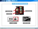
Page 17: ...Ⅱ Inside of Tanzanite Model Control Connection Panel Control Connection Panel ...

Page 18: ...MI connection When using an HDMI DVI cable connection you must use the HDMI IN 2 jack What is HDMI High Definition Multimedia interface allows the transmission of high definition digital video data and multiple channels of digital audio The HDMI DVI terminal supports DVI connection to an extended device with the appropriate cable not supplied The difference between HDMI and DVI is that the HDMI de...

Page 19: ...some channels Scrambled Signal is displayed on the screen The pairing information containing a telephone number CI CARD ID Host ID and other information will be displayed in about 2 3 minutes If an error message is displayed please contact your service provider When the channel information configuration has finished the message Updating Completed is displayed indicating that the channel list is no...

Page 20: ...t connectors on the A V device 7 H eadphones jack Headphone may be connected to the headphone output on your set While the head phone is connected the sound from the built in speakers will be disabled 8 Kensington Lock depending on the model The Kensington lock optional is a device used to physically fix the system when used in a public place If you want to use a locking device contact the dealer ...

Page 21: ...n your component devices DTV or DVD are sometimes labeled Y B Y and R Y or Y Cb and Cr Connect RCA audio cables optional to R AUDIO L on the rear of your set and the other ends to corresponding audio out connectors on the DTV or DVD 10 SERVICE Connector for SERVICE only 11 PC IN PC AUDIO Connect to the video and audio output jack on your PC 12 DIGITAL AUDIO OUT OPTICAL DTV Only Connect to a Digita...

Page 22: ...ut Monitor out SPDIF out EMMA2SL CPUI DEMUX MPEG A V DECODER PAL ENCODER HOST INTERFACE PERIPHERALS PCMCIA TS FLASH 4MB DDR 32MB OSC 27MHz PWM UART MAX232 FILTER AUDIO DAC EW8521 R G B Hsync Vsync Y Pb Pr Y C CVBS EXT 1 2 SC1 CVBS FB SC2 CVBS DTV R L SIF SPDIF Y Pb Pr CVBS Rx Tx I2S DTV Part MAIN Part SC1 RGB VIDEO CVBS BA7657F Audio SW 74HC4052 I2S Sound Flash MX25L 16M Bit EXT1_out Monitor out H...

Page 23: ...SMPS Main Board Panel Inner Feature of 32 Inner Feature of 32 Ⅱ Inside of Tanzanite Model SPEAKER SPEAKER MAIN B D SMPS ...

Page 24: ...SMPS Main Board Panel Inner Feature of 37 Inner Feature of 37 Ⅱ Inside of Tanzanite Model SPEAKER SPEAKER MAIN B D SMPS ...

Page 25: ...IP Main Board Panel Inner Feature of 40 Inner Feature of 40 Ⅱ Inside of Tanzanite Model SPEAKER MAIN B D IP B D SPEAKER ...

Page 26: ...ustment Blue Green Pink Dynamic Contrast Enhancing Contrast Ratio Up to 2000 1 Brightness Sensor Sensing the outside brightness and controlling brightness Some Functions of Tanzanite Some Functions of Tanzanite Ⅱ Inside of Tanzanite Model ...

Page 27: ...stics and contrast level of input signal Enhancing dynamic contrast Up to 1600 1 In Out In Out Out In Out In Luma Y Y Y Mid range dynamic range Enhancement Contrast Enhancement Dimming Luma Luma Ⅱ Inside of Tanzanite Model Some Functions of Tanzanite Some Functions of Tanzanite ...

Page 28: ...OUT 110 190 120 200 255 255 IN Gamma Curve Contrast Enhancement Factor Ⅱ Inside of Tanzanite Model Some Functions of Tanzanite Some Functions of Tanzanite ...

Page 29: ...g 255 0 MEAN 255 0 MEAN Input Output MEAN U C MEAN V 4 0 Analog Dimming MEAN Duty 98 50 PWM Dimming Input Output MEAN U C Dark Image Bright Image Ⅱ Inside of Tanzanite Model Some Functions of Tanzanite Some Functions of Tanzanite ...

Page 30: ...es the selector left or right on the OSD Increase or decrease the values of the selected function VOL Increase or decrease the level of audio volume in the Anynet mode You can control only TV volume 4 Moves the selector up or down on the OSD CH Increase or decrease the channel number 5 Power 1 Turn ON OFF the TV 2 Indicates the status of the Monitor Black Normal Operation Red Power Off or Disconne...

Page 31: ...djusts the outline of objects to either sharpen them or make them more dull Color Adjusts the colors making them lighter or darker Tint Adjusts the color of objects making them more red or greem for a more natural look Detailed settings Black Adjust Off Low Medium High Dynamic Contrast Off Low Medium High Gamma 3 to 3 Color Space Auto Wide Custom White Balance R G B Offset R G B Gain Reset Flesh T...

Page 32: ...ital NR Off Low Medium High Auto DNIe Off Demo On HDMI Black Level Normal Low Blue Only Mode Off On Blue Only Mode You can emphasize the Blue color by switching off the Red and Green colors This function is for AV device measurement experts Reset You can return to the factory defaults picture settings Ⅱ Inside of Tanzanite Model Some Functions of Tanzanite Some Functions of Tanzanite ...

Page 33: ... Custom setting Equalizer Change EQ and balance SRS TSXT Select mode of SRS On Off Auto Volume On Off TV Speaker On Off Sound Select Main Sub ATV Only 3 Channel Country Auto Store Manual Store Channel Manager Sort Name Fine tune LNA Ⅱ Inside of Tanzanite Model Some Functions of Tanzanite Some Functions of Tanzanite ...

Page 34: ...ower on off melody sound can be adjusted Off Low Medium High Entertainment Enables you to select the optimal display and sound for sports cinema and games Energy Saving Adjusts the screen brightness depending on the surrounding lighting conditions Off Low Medium High Auto PIP PIP Source Size Position Programme ATV Only Ⅱ Inside of Tanzanite Model Some Functions of Tanzanite Some Functions of Tanza...

Page 35: ...to the input jacks to make your input source selection easier Anynet HDMI CEC Anynet is an AV network system that enables an easy to use AV interface for users by controlling all connected AV devices through the Anynet menu when Samsung Electronics AV devices are connected Ⅱ Inside of Tanzanite Model Some Functions of Tanzanite Some Functions of Tanzanite ...

Page 36: ...Key parts of Key parts of Tanzanite Tanzanite SCALER SEMS01 DTV DECODER D61211GM SOUND AMP NTP3100 DTV COMP SW BA7657 Ⅱ Inside of Tanzanite Model ...

Page 37: ...audio decoder two video de interlacers two scaling engines the MStarACE 3 color engine an on screen display controller an 8 bit MCU and a built in output panel interface By use of external frame buffer IP POP is provided for multimedia applications Furthermore 3 D video decoding and processing are fulfilled for high quality TV applications To further reduce system costs the MST69981CL also integra...

Page 38: ...r 10 bit triple ADC for TV and RGB YPbPr 10 bit video data processing Integrated DVI HDCP HDMI compliant receiver High quality dual scaling engines dual 3 D video de interlacers 3 D Video noise reduction Full function PIP PBP POP MStarACE 3 picture color processing engine Embedded On screen display controller OSD engine Built in MCU supports PWM GPIO Built in dual link 8 bit LVDS transmitter 5 Vol...

Page 39: ...d V chip Macrovision detection CVBS video output Multi Standard TV Sound Decoder Supports BTSC NICAM A2 EIA J demodulation and decoding FM stereo SAP demodulation L Rx4 mono and SIFx2 audio input L Rx3 loudspeaker and line output Supports sub woofer output Built in audio output DAC s Audio processing for loudspeaker channel including volume balance mute tone EQ and virtual stereo surround Optional...

Page 40: ...rogrammable delay for audio video synchronization Analog RGB Compliant Input Ports Three analog ports support up to UXGA Fast blanking and function selection switch support full SCART functions Supports HDTV RGB YPbPr YCbCr up to 1080P Supports Composite Sync and SOG Sync on Green separator Automatic color calibration Ⅱ Inside of Tanzanite Model ...

Page 41: ...ompliant receiver High bandwidth Digital Content Protection HDCP 1 1 compliant receiver High Definition Multimedia Interface HDMI 1 2 compliant receiver with CEC support Long cable tolerant robust receiving Support HDTV up to 1080P Auto Configuration Auto Detection Auto input signal format and mode detection Auto tuning function including phasing positioning offset gain and jitter detection Sync D...

Page 42: ...able shrink zoom capabilities Nonlinear video scaling supports various modes including Panorama Video Processing Conversion 3 D motion adaptive video de interlacers Edge oriented adaptive algorithm for smooth low angle edges Automatic 3 2 pull down 2 2 pull down detection and recovery PIP PBP POP with programmable size and location supports multi video applications Ⅱ Inside of Tanzanite Model ...

Page 43: ...and details Vivid skin tone Sharp edge Enhanced depth of field perception Accurate and independent color control sRGB compliance allows end user to experience the same colors as viewed on CRTs and other displays Programmable 12 bit RGB gamma CLUT DLC with 32 segment histogram 3 D video noise reduction Frame rate conversion Ⅱ Inside of Tanzanite Model ...

Page 44: ...nd alpha blending capability Supports blinking and scrolling for closed caption applications 8 bit LVDS TTL Panel Interface Supports dual link LVDS up to UXGA 1600x1200 WSXGA 1680x1050 Supports 8 bit single TTL panel Supports 2 data output formats Thine TI data mappings Compatible with TIA EIA With 6 8 bits options Reduced swing for LVDS for low EMI Supports flexible spread spectrum frequency with...

Page 45: ... system control SPI bus for external flash Supports external MCU option controlled through 4 wire double data rate direct MCU bus or 8 bit direct MCU bus External Connection Component 16 bit data bus for external frame buffer SDR or DDR DRAM All system clocks synthesized from a single external clock Ⅱ Inside of Tanzanite Model ...

Page 46: ...gh performance and cost effective digital set top box or integrated digital TV FEATURES MPEG1 and MPEG2 TS PS compliant High performance MIPS32 4KEc main CPU core High performance MIPS32 4KEm sub CPU core Integrated DVB descrambling with family options for Irdeto 36 PID filters 32 section filters Video Outputs 4 DACs for RGB component video S video and composite output with support for PAL NTSC an...

Page 47: ...3 only Audio Output 2 channel PCM and SPDIF Peripherals support two fast UARTs with 16byte FIFOs two I2C interfaces two Smart Card interfaces infrared receiver three wire clocked serial interface System timers RTC and Watchdog timer Motorola Intel Bus Ⅱ Inside of Tanzanite Model ...

Page 48: ...DECODER D61211GM Ⅱ Inside of Tanzanite Model ...

Page 49: ...sets 4KByte instruction cache 4KByte data cache 2 way cache accessing EJTAG debug support Sub Processor High Performance MIPS32 4KEm CPU core for audio MPEG decoding 4KByte instruction cache 4KByte data cache 8KByte scratch pad memory support Unified Memory Interface Supports 8 and 16bit bus width DDR SDRAM Unified CPU MPEG Graphics memory Ⅱ Inside of Tanzanite Model ...

Page 50: ...al address area 64Mbyte for ROM Supports normal page and flash ROM Supports NOR and NAND flash ROM 2 chip select signals for ROM 8MByte total address area for GIO 2 chip select signals for GIO PCMCIA support 16 bit PC Card only DMA Supports DMA transfers to from GIO and memory to memory Ⅱ Inside of Tanzanite Model ...

Page 51: ... port Supports MPEG2 TS Maximum input bit rate 100Mbit sec High Speed Data port output for external IEEE1394 link devices 36 PID filters 1 Video PID 2 Audio PIDs 1 PCR PID 32 general PIDs 32 section filters 8 Byte 16 byte depth Descrambler Supports decryption with 16 key pairs Ⅱ Inside of Tanzanite Model ...

Page 52: ...ant Supports MPEG 1 and 2 elementary streams Audio Processor MPEG 1 and 2 layer 1 and 2 PCM L R audio output SPDIF output Test tone and Mixing Graphics engine 2 D image data transfer Colour space conversion RGB32 to YCbCr Colour expansion Ⅱ Inside of Tanzanite Model ...

Page 53: ...ration 16 Programmable Biquad Filters Speaker Compensation DC cut LPF HPF Parametric Equalizer 100 dB Dynamic Range Adaptive Loudness Compensator based on Psycho Acoustics Dynamic range control Loudness Applications Plasma TV LCD TV Docking Station Mini Component Audio Ⅱ Inside of Tanzanite Model ...

Page 54: ... power full bridge MOSFET stages NTP3100 receives 2 channel serial audio data with sampling frequency from 8 kHz to 192kHz It delivers 2x20W in stereo mode without heat sink Combining use of built in mixer and biquad filters can make additional preprocessing like bass management loudness control loud speaker response compensation and preset parametric equalizers possible All the functions of NTP31...

Page 55: ...SOUND AMP NTP3100 Package 56 pin MLF 8mm by 8mm Ⅱ Inside of Tanzanite Model ...

Page 56: ...SOUND AMP NTP3100 PIN DESCRIPTIONS Ⅱ Inside of Tanzanite Model ...

Page 57: ...DTV COMP SW BA7657 BLOCK DIAGRAM Ⅱ Inside of Tanzanite Model ...

Page 58: ...es on a single 5V power supply Internal broadband RGB switch frequency characteristics 250MHz 3dB Internal HD VD switch Internal synchronization separator for synchronizing signals superimposed onto G signals Ⅱ Inside of Tanzanite Model ...

Page 59: ...BOARD DESCRIPTION Ⅲ Board description ...

Page 60: ...1 Main B D Layout 2 Main B D Pin Characteristic 3 SMPS Board 4 Power B D Layout 5 Power B D Pin Characteristic Ⅲ Board description CONTENTS CONTENTS ...

Page 61: ...CONTROL SPEAKER JACK MAIN BOARD LAYOUT MAIN BOARD LAYOUT ...

Page 62: ...scription CN1001 Main Board power supply CN2001 SPEAKER CONNECTOR MAIN BOARD LAYOUT MAIN BOARD LAYOUT PIN 1 2 3 4 5 6 7 8 9 NAM E DIMMIN G GND GND GND 13V 13V 13V 3 3V SW PIN 1 2 3 4 NAM E R OUT R OUT L OUT L OUT ...

Page 63: ... board power supply KEY INPUT1 2 key control form the Menu channel up down Etc IR remote control signal LED_STB control the timing and standby LED color PIN 1 2 3 4 NAME IR GND A5V LED_STB PIN 5 6 7 8 NAME BUZZER KEY_INPUT 1 KEY_INPUT2 GND MAIN BOARD LAYOUT MAIN BOARD LAYOUT ...

Page 64: ...ND FBE_ODD_TXCLK FBE_ODD_TXCLK FBE_ODD_TX3 FBE_ODD_TX3 FBE_EVEN_TX0 PIN 13 14 15 16 17 18 NAME FBE_EVEN_TX0 GND FBE_EVEN_TX1 FBE_EVEN_TX1 GND FBE_EVEN_TX2 PIN 19 20 21 22 23 24 NAME FBE_EVEN_TX2 FBE_EVEN_TXCLK FBE_EVEN_TXCLK FBE_EVEN_TX3 FBE_EVEN_TX3 GND PIN 25 26 27 28 29 30 NAME GND GND N C PANEL_Vcc PANEL_Vcc PANEL_Vcc MAIN BOARD LAYOUT MAIN BOARD LAYOUT ...

Page 65: ...40Vac 1 2 INPUT FREQUENCY RANGE 47Hz TO 63Hz NORMAL FREQUENCY 50 60Hz 1 3 MAX INPUT AC CURRENT 2 0Arms 90VAC 1 4 INRUSH CURRENT PEAK INRUSH CURRENT AT ANY ALLOWABLE OPERATING TEMPERATURE SHALL NOT OPEN LINE FUSE RECIFIER DIODE OR CAUSE PERMANENT DAMAGE TO THE SUPPLY 1 5 DPMS DISSAPATION LESS THAN 0 9 WATT AT 13V 15mA AT 230Vac 60Hz OR NO LOAD 0 5W MAX AT 230Vac 60Hz ...

Page 66: ...Ⅲ Board description IP SPEC IP SPEC MAIN BOARD LAYOUT MAIN BOARD LAYOUT OUTPUT CHARACTERISTICS ...

Page 67: ...Ⅲ Board description IP SPEC IP SPEC MAIN BOARD LAYOUT MAIN BOARD LAYOUT ...

Page 68: ...Ⅲ Board description IP SPEC IP SPEC MAIN BOARD LAYOUT MAIN BOARD LAYOUT ...

Page 69: ...Ⅲ Board description IP SPEC IP SPEC MAIN BOARD LAYOUT MAIN BOARD LAYOUT ...

Page 70: ...Ⅲ Board description IP SPEC IP SPEC MAIN BOARD LAYOUT MAIN BOARD LAYOUT ...

Page 71: ...Ⅲ Board description IP SPEC IP SPEC MAIN BOARD LAYOUT MAIN BOARD LAYOUT ...

Page 72: ...Ⅲ Board description IP SPEC IP SPEC MAIN BOARD LAYOUT MAIN BOARD LAYOUT ...

Page 73: ...200 09 YBST200 PIN DEFINITION PIN 1 BRT_ADJ PWM Dimming control 0 4 5v PIN 2 3 4 GND PIN 5 6 7 13V PIN 8 BRT_ADJ ANALOG Dimming control 0 3 3v PIN 9 BL NO OFF CFLL Drive SIGNAL Active HIGH 2 CN201 CN202 YEONHO 35002WR 04L 3 PIN DEFINITION PIN 1 3 HOT HIGH VOLTAGE FOR CCFL PIN 2 4 COLD LOW VOLTAGE FOR CCFL 4 AC SOCKET 3 PIN SOLTEAM ST 01DJ BBBV 3 ...

Page 74: ...magnetic Field Immunity Test RS Level 2 criterion A WITH SYSTEM IEC61000 4 4 Electrical Fast Transient Burst Immunity Test EFT Level 2 1KV 5KHz on AC power port for 1 minute criterion B WITH SYSTEM IEC61000 4 5 Surge Immunity Test PLD WITH SYSTEM 1 L to N 1 0KV 1 2 50uS criterion B 2 L N to FG 2 0KV 1 2 50uS criterion B IEC61000 4 6 Conducted Disturbances Induced by Radio Frequency Field Immunity ...

Page 75: ...IV Disassembly DISASSEMBLY ...

Page 76: ...IV Disassembly Disassembly Tanzanite ...

Page 77: ...IV Disassembly ...

Page 78: ...IV Disassembly ...

Page 79: ...IV Disassembly ...

Page 80: ...IV Disassembly ...

Page 81: ...V Trouble Shooting TROUBLE SHOOTING ...

Page 82: ...CONTENTS CONTENTS V Trouble Shooting I Power Trouble Shooting II Analog Part III Digital Part IV Sound Part V Flow Chart Waveforms VI White Balance ...

Page 83: ... main board power output on the board When you check main board power small power IC There are two types of power IC One is PWM type another is regulator type PWM type should check after inductor Regulator type should check on the output pin Check each Voltage output 1 PWM Type 2 Regulator Type Check After Inductor Check On Pin V Trouble Shooting ...

Page 84: ...ignal Use reference signal input EX 16 Gray Check Signal Level and sync Check Signal path until input of Video decoder Tuner Switch Video Decoder AV Connecter Switch Video Decoder Scart Switch Video Decoder 16 Gray Patten 16 Gray Wave Form H sync Gray Level V Trouble Shooting ...

Page 85: ...ync V sync and Clock for basic Each digital video ICs connected with data line H sync V sync and Clock line Check H sync period V sync period Clock period If period is out of spec Change the IC H Sync 1 Period 15 63kHz V Sync 1 Period 50Hz Clock 1 Period 13 5MHz V Trouble Shooting This example is Normal PAL TV signal Sync and Clock ...

Page 86: ...x is composed of Sound Processor AMP Speakers If there is no sound or sound noise Trace the sound path Input Sound Processor AMP Speaker V Trouble Shooting TUNER VIDEO S VIDEO SCART COMPONENT PC HDMI SOUND AMP STV Sound Processor SPEAKER ...

Page 87: ...V Trouble Shooting ...

Page 88: ...V Trouble Shooting R G B Output Signal ...

Page 89: ...V Trouble Shooting Digital Output Data Signal of HDMI Data ...

Page 90: ...V Trouble Shooting CVBS Output Signal Tuner CVBS Output Signal ...

Page 91: ...V Trouble Shooting Digital Output Data Analog Signal Y C ...

Page 92: ...V Trouble Shooting The Signal Inputed to IC2002 The Signal Inputed to IC2001 ...

Page 93: ...V Trouble Shooting ...

Page 94: ...HOW TO UPGRADE ...

Page 95: ...HOW TO UPGRADE HOW TO UPGRADE VI How to Upgrade 1 ATV S W Order Description ETC 1 Open the Flash Downloader 2 Connect DDC Manager to the TV Set with D SUB Cable ...

Page 96: ...OW TO UPGRADE HOW TO UPGRADE VI How to Upgrade 3 1 Choose the ATV S W 2 Check the download port LPT1 3 Click Mstar for Micom 4 Click Connect Before clicking the icon TV shoud be turned on 5 Click Program ...

Page 97: ...HOW TO UPGRADE HOW TO UPGRADE VI How to Upgrade 2 DTV S W Order Description ETC 1 Connect PC and TV Set with Serial cable TV should be turned on 2 Open the Samsung Set top Box upgrade Wizard ...

Page 98: ...de 3 1 Choose the DTV S W by clicking Browse 2 After choosing the S W click the Next icon 4 When it display Scanning power off and on the TV set It doesn t matter soft or hard power off and on 5 After scaning COM port Model and Version click Next ...

Page 99: ...fter S W Upgrade How to Access Service Mode Entering Factory Mode Power OFF INFO MENU MUTE Power ON Factory Data 1 Option Table Service 2 WB Adjust 3 Information 4 Advanced Menu If you want to enter here press 0000 VI How to Upgrade ...

Page 100: ...HOW TO UPGRADE HOW TO UPGRADE How to Initialize Click 1 Option Table Service Factory Reset in Factory Menu You can make every setting in Factory Initial Status VI How to Upgrade ...

Page 101: ...ATTACHMENT ...

Page 102: ...CONTENTS CONTENTS I What is HDMI II What is a TrusurroundXT ...

Page 103: ...A REMOTE CONTROL NONE AV LINK CAPABILITIES REPLACES INFRARED REPEATERS INTEGRATED REMOTE CONTROL SYSTEM CONNECTOR FUTURE COMPATIBILITY NONE ACCOMMODATES ATSC DTV FORMATS SUPPORTS 8 CHANNEL AUDIO SPARE BANDWIDTH FOR FUTURE APP 55 EXTRA AFTER HD TRANSMISSION What is HDMI Attachment ...

Page 104: ...HDMI block diagram What is HDMI Attachment ...

Page 105: ...figuration and status exchange between a single Source and a single Sink The optional CEC protocol provides high level control functions between all of the various audiovisual products in a user s environment Audio video and auxiliary data is transmitted across the three TMDS data channels The video pixel clock is transmitted on the TMDS clock channel and is used by the receiver as a frequency ref...

Page 106: ...Connector Drawings All dimensions in millimeters What is HDMI Attachment ...

Page 107: ... D2_RXCLK GND 2 D2_RX2 GND 12 D2_RXCLK 3 D2_RX2 13 No connection 4 D2_RX1 14 No connection 5 D2_RX1 GND 15 HDMI_DDC_SCL 6 D2_RX1 16 HDMI_DDC_SDA 7 D2_RX0 17 HDMI_DDC_GND 8 D2_RX0 GND 18 HDMI VCC 5V 9 D2_RX0 19 Ident_HDMI 10 D2_RXCLK 20 Common GND What is HDMI Attachment ...

Page 108: ...HDMI Encoder Decoder Overview What is HDMI Attachment ...

Page 109: ...e of several different coding techniques The input stream to the Source s encoding logic will contain video pixel packet and control data The packet data consists of audio and auxiliary data and associated error correction codes These data items are processed in a variety of ways and are presented to the TMDS encoder as either 2 bits of control data 4 bits of packet data or 8 bits of video data pe...

Page 110: ...Example TMDS periods in 720x480p video frame What is HDMI Attachment ...

Page 111: ...eriods Video Data Periods use transition minimized coding to encode 8 bits per channel or 24 bits total per pixel Data Island Periods are encoded using a similar transition minimized coding TMDS Error Reduction Coding TERC4 which transmits 4 bits per channel or 12 bits total per pixel clock period During Control Periods 2 bits per channel or 6 bits total are encoded per pixel clock using a transit...

Page 112: ...pecific minimum requirements have been specified for Sources and Sinks Primary Video Format Timings 640x480p 59 94 60Hz 1280x720p 59 94 60Hz 1920x1080i 59 94 60Hz 720x480p 59 94 60Hz 720 1440 x480i 59 94 60Hz 1280x720p 50Hz 1920x1080i 50Hz 720x576p 50Hz 720 1440 x576i 50Hz What is HDMI Attachment ...

Page 113: ...ther IEC 60958 format or IEC 61937 format If an HDMI Sink supports audio reception across any input then it shall support audio reception from all HDMI inputs Basic Audio is defined as two channel L PCM audio at sample rates of 32kHz 44 1kHz or 48kHz with a sample size of at least 16 bits For EIA CEA 861B references to DTV devices Basic Audio is defined as two channel L PCM audio at sample rates o...

Page 114: ...device an HDMI device shall operate according to the DVI 1 0 specification with the following exception these devices are not required to comply with DVI 1 0 rules regarding Monitor scaling requirements Physical Interconnect specifications System Low Pixel Format Support Requirements Furthermore for HDMI devices which do not have a BIOS or operating system there are the following additional except...

Page 115: ... speakers TruSurround XT bridges this gap It processes any multichannel audio source as is usually found on DVDs and transforms the material into breathtaking virtual surround sound from just two speakers or headphones Based upon the patented TruSurround technology from SRS Labs which is the established standard for virtual surround sound TruSurround XT also includes the unique features of SRS Dia...

Page 116: ...ltichannel formats up to 6 1 channels SRS Dialog Clarity Enhancement Playback of dialog often suffers due to competing signals from other speakers In addition feature film soundtracks are mixed specifically for cinema playback and are loaded with the latest advancements in special audio effects When translated over home theatre or computers systems dialog may become unintelligible This patented SR...

Page 117: ...te it even if it is below the speaker s low frequency limitations WOW WOW is an award winning stereo enhancement technology that significantly improves the performance of stereo non surround sound encoded material signals through any two speaker system including headphones It extends the sound image in both the horizontal and vertical planes well beyond the speakers themselves In addition WOW inco...

Reviews: