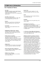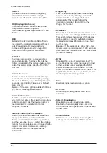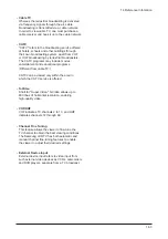
14 Reference Infomation
14-6
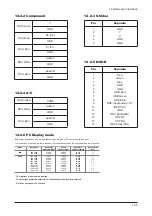
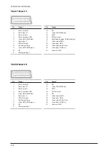
14-2-7 Scart 1
14-2-8 Scart 2
Pin
Signal
1
Audio output R
2
Audio input R
3
Audio output L
4
Audio common GND
5
Video GND (RGB blue)
6
Audio input L
7
RGB blue input
8
Switching voltage
9
Video GND (RGB green)
10
NC
11
RGB green input
Pin
Signal
12
NC
13
Video GND (RGB red)
14
GND
15
RGB red input
16
Fast Blanking signal (RGB switching)
17
Video output GND
18
Video input GND
19
Video output (CVBS out)
20
Video input (CVBS in)
21
Common GND
Pin
Signal
1
Audio output R
2
Audio input R
3
Audio output L
4
Audio common GND
5
Video GND (RGB blue)
6
Audio input L
7
RGB blue input
8
Switching voltage
9
Video GND (RGB green)
10
NC
11
RGB green input
Pin
Signal
12
NC
13
Video GND (RGB red)
14
GND
15
RGB red input
16
NC
17
Video output GND
18
Video input GND
19
Video output (CVBS out)
20
Video input (CVBS in)
21
Common GND
Summary of Contents for LE40N87BDX
Page 13: ...2 Product Specifications 2 8 Memo...
Page 37: ...11 Disassembly and Reassembly 11 6 Memo...
Page 41: ...4 Troubleshooting 4 4 WAVEFORMS 1 R G B Output Signal of IC2001...
Page 43: ...4 Troubleshooting 4 6 2 Digital Output Data of IC4001 3 Signal of HDMI Data...
Page 45: ...4 Troubleshooting 4 8 WAVEFORMS 4 Tuner_CVBS Output Signal 3 CVBS Output Signal...
Page 47: ...4 Troubleshooting 4 10 WAVEFORMS 4 CVBS Output Signal...
Page 49: ...4 Troubleshooting 4 12 2 Digital Output Data of IC2001 5 Analog Signal Y C to IC2001 WAVEFORMS...
Page 67: ...3 Alignments and Adjustments 3 16 Memo...
Page 69: ...7 Block Diagrams 7 2 Memo...
Page 71: ...12 PCB Diagram 12 2 12 2 IP Board Diagram 37...
Page 72: ...12 PCB Diagram 12 3 12 3 IP Board Diagram 40...
Page 73: ...12 PCB Diagram 12 4 12 4 IP Board Diagram 46...
Page 74: ...12 PCB Diagram 12 5 12 5 IP Board Diagram 52...
Page 75: ...12 PCB Diagram 12 6 Memo...
Page 81: ...8 Wiring Diagrams 8 6 8 4 Power Board Layout...
Page 84: ...8 9 8 Wiring Diagrams...
Page 87: ...8 Wiring Diagrams 8 12 Memo...
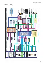
Page 122: ...13 Circuit Descriptions 13 3 13 2 Main Block...
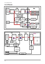
Page 123: ...13 Circuit Descriptions 13 4 13 3 IP Board...
Page 129: ...10 Operating Instructions and Installation 10 6 Memo...
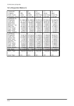
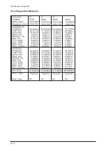
Page 137: ...14 Reference Infomation 14 8 14 3 2 Supported Modes 1...
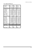
Page 138: ...14 Reference Infomation 14 9 14 3 3 Supported Modes 2...
Page 139: ...14 Reference Infomation 14 10 14 3 4 Supported Modes 3...
Page 150: ...Memo 1 Precautions 1 4...

