71
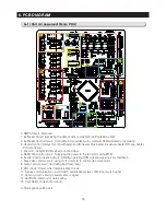
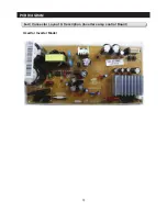
PCB DIAGRAM
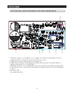
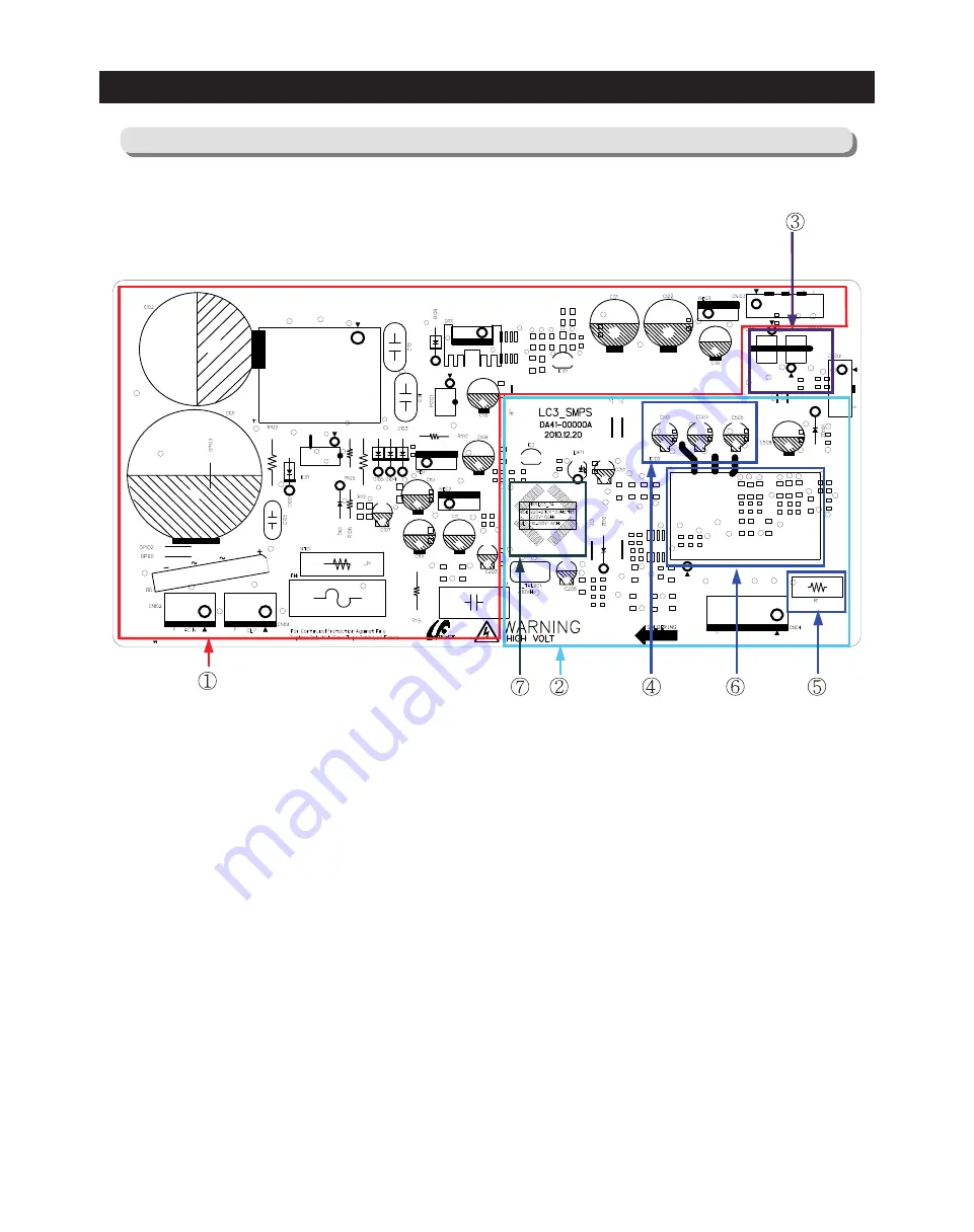
6-2) Connector Layout & Descriptions of Inverter Controller Board
1. PCB Power Supply : From the SMPS circuit, it supplies 15V and 5V for the Main PBA control and
supplies15V and 5V to the Inverter circuit for the Compressor control.
2. Inverter Control Circuit : Fridge Compressor Control Circuit.
3. COMP Driving / Feedback CircuitIt receives the COMP operation signals from the Main PBA and
feedbacks the inverter errors to the Main PBA.
4. BOOTSTRAP Charger : It is an independent power circuit for the driving of the IMP High-Phase IGBT.
5. Current Pickup Circuit : It pickups the currents taken by the Shunt resistance and does the PWM DUTY
control.
6. IPM (FNE41060)
7. Micom (MN103SFC2D)
Summary of Contents for LS3165H52HR
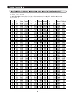
Page 52: ...54 TROUBLESHOOTING Diode Voltage of IPM ...
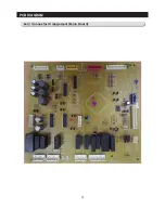
Page 69: ...72 PCB DIAGRAM 6 3 Connector Arrangement Main Board ...
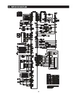
Page 71: ...69 5 WIRING DIAGRAM ...
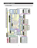
Page 72: ...74 7 1 Block Diagram 7 SCHEMATIC DIAGRAM ...
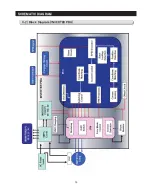
Page 73: ...75 SCHEMATIC DIAGRAM 7 2 Block Diagram INVERTER PBA DC 13 2V 5V ...
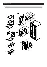
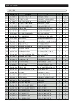
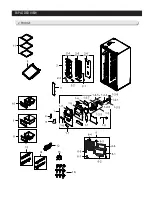
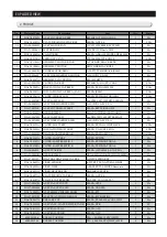
Page 76: ...EXPLODED VIEW 1 FREEZER ...
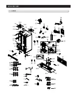
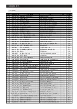
Page 78: ...15 EXPLODED VIEW 2 FRIDGE 16 ...
Page 83: ...1 7 1 8 4 5 7 3 8 2 8 3 11 10 12 EXPLODED VIEW 4 DOOR FRE 4 6 9 3 13 ...
Page 85: ...3 4 5 1 3 2 2 3 3 3 4 3 4 1 3 1 6 EXPLODED VIEW 5 DOOR REF IN ...
Page 87: ...3 3 1 2 1 1 1 4 1 5 1 6 1 7 4 EXPLODED VIEW 6 DOOR REF OUT 1 ...

