background image

4 Alignments and Adjustments

4-8

LT17N23W

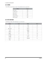
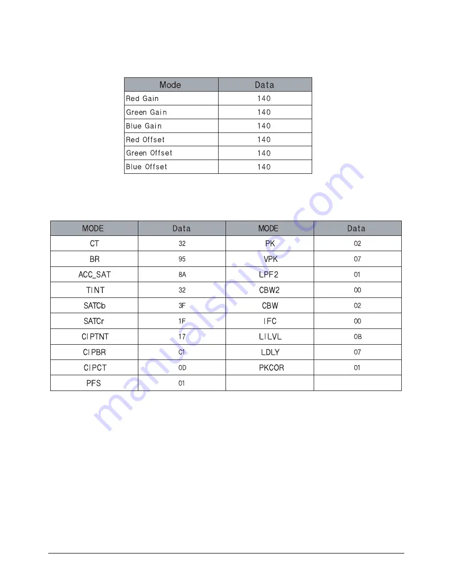
4-3-4 PW565

* The PW565 output data are fixed to the default and are not adjusted.

4-3-5 VPC 3230-MAIN

* The Data are fixed to the default and are not adjusted.

Summary of Contents for LT17N23W

Page 1: ...TFT LCD TV MONITOR CONTENTS 1 Precautions 2 Product Specifications 3 Disassembly Reassembly 4 Alignment Adjustments 5 Troubleshooting 6 Exploded View Parts List 7 Parts List 8 Block Diagram 9 Wiring D...

Page 2: ...P1_Y NC 14V_INVERTER GND 14V_INVERTER NC GND COMP1_L GND D4_L GND NC GND COMP1_R GND D4_R GND PC_RED PC_GREEN PC_BLUE GND GND GND GND GND PC_5V IDENT_PC GND DDC_TXO H_SYNC DDC_RXO V_SYNC CN804 CN805 K...

Page 3: ...or main ass y BN91 00716A Yes No Does each proper DC 5V appear at L603 Change IC602 or main ass y BN91 00716A Yes No Does each proper DC 3 3V 33V appear at C618 C621 Change IC603 IC604 or main ass y B...

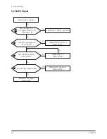
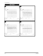
Page 4: ...5 Troubleshooting 5 2 LT17N23W WAVEFORMS 1 1 1 2 1 3 1 4...

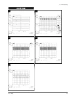
Page 5: ...WAVEFORMS 1 5 1 6 1 7 5 Troubleshooting LT17N23W 5 3...

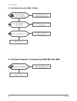
Page 6: ...l cable Yes No Does the signal appear at RA101 RA107 Change IC101 or main ass y BN91 00716A A Yes No Does the signal appear at RA514 RA519 Change main ass y BN91 00716A Yes No Does the signal appear a...

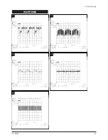
Page 7: ...5 Troubleshooting LT17N23W 5 5 WAVEFORMS 2 1 2 2 2 3 2 5 2 4...

Page 8: ...pear at RA201 RA204 Change IC305 or replace main board with new one Yes No Does the signal appear at X201 Change X201 or replace main board with new one Yes No 3 1 3 3 3 2 3 4 3 5 5 3 2 No Video Compo...

Page 9: ...5 Troubleshooting LT17N23W 5 7 WAVEFORMS 3 1 3 2 3 3 3 4 3 5...

Page 10: ...5 Troubleshooting 5 8 LT17N23W WAVEFORMS 3 6 3 7 3 8 3 9...

Page 11: ...C751 C752 AV C753 C754 D connector input C755 C766 comp1 Change IC703 or replace main board with new one Yes No Does the signal appear at C701 C704 Sound_R C724 C725 Sound_L Change IC701 or replace ca...

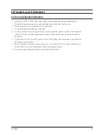
Page 12: ...essential 4 Avoid overload Excessive signal from a sweep generator might overload the front end of the TV When inserting signal markers do not allow the marker generator to distort test result 5 Conn...

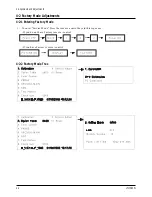
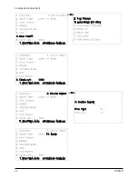
Page 13: ...17N23W 4 2 Factory Mode Adjustments 4 2 1 Entering Factory Mode 1 To enter Service Mode Press the remote control keys in this sequence If you do not have Factory remote control If you have Factory rem...

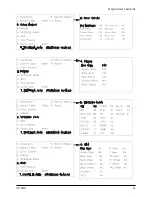
Page 14: ...4 Alignments and Adjustments LT17N23W 4 3...

Page 15: ...4 Alignments and Adjustments 4 4 LT17N23W...

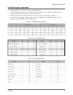
Page 16: ...nt adjustments are requried for RF DTV Component 1 D4 and PC modes 3 Optimum condition data for each mode are saved as default values Refer to Table 2 3 4 As the RF mode is applied with the same vlaue...

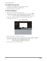
Page 17: ...720 Mode Pattern 36 PC Mode Model 21 1024 768 Mode Pattern 16 Picture 4 1 b Enter factory Calibration confirm the ADC data DTV PC Mode Only ADC default value Table 4 3 2 Adjust the white balance of RF...

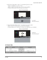
Page 18: ...t and is not adjusted d Adjust the high light Refer to table 1 2 in adjustment position by mode Adjust red gain x and blue gain y to the color coordinates The green gain and sub Contrast Y are fixed t...

Page 19: ...4 Alignments and Adjustments 4 8 LT17N23W 4 3 4 PW565 The PW565 output data are fixed to the default and are not adjusted 4 3 5 VPC 3230 MAIN The Data are fixed to the default and are not adjusted...

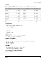
Page 20: ...p 4 3 8 Check sum XXXX Displays the current check sum size of the MICOM Varies depending on program update 4 3 9 Service Adjustement Used where it is difficult to receive stereo sound Adjust the Pilot...

Page 21: ...8 Block Diagram This Document can not be used without Samsung s authorization LT17N23W 8 1...

Page 22: ...34 16V 22 R204 A5V C128 100nF C230 100pF 50V 16V C159 10uF R933 3 3UH BD102 SEN 6 SMS VDD 12 7 VIDEO Vin 13 1 Vss_1 11 Vss_2 1 16W 100 BOX 17 8 CSYNC GREEN 2 5 HIN LPF 9 18 RED RREF 10 15 SCK SDA 14 1...

Page 23: ...E R565 100 A B 2 C 3 T872 1 SGM32F1E104 2A FT504 1 R567 2 2K R566 2 2K 1 16W 47 R553 10K R550 1 16W 1K R951 1 16W 1nF C517 C527 100nF 1 2 3 4 5 6 7 8 C562 RA509 SUPLECODE C541 R505 0 T507 1 R534 0 1 2...

Page 24: ...nF C743 100nF C639 16V D603 SS24 BD606 1 A 2 B 16V 47uF C636 1 BLM41P600S 10uF C770 TP827 SUPLVAL BLM41P600S 1 A 2 B R739 1 16W 1K BD602 T531 1 100 R731 C755 C635 4 7uF 25V IC607 2 GND IN 1 OUT 3 100u...

Page 25: ...3 SIG_2 SIG_3 5 6 SIG_4 8 SIG_5 9 SIG_6 jack9p_b CN802 1 GND_1 GND_2 4 1 L805 N U91 1 T806 VIDEO_OUT VT 4 L816 N GND3 21 GND4 22 1 NC_1 9 NC_2 NC_3 10 NC_4 11 12 NC_5 NC_6 13 SCL 6 7 SDA 16 SUPLVAL 2...

Page 26: ...SIS BN91 00716A ASSY SHIELD BN91 00718A ASSY BOARD P AV JACK BN96 00503A ASSY BOX BN92 00927A ASSY LABEL BN92 00929A REMOCON BN59 00374A ASSY ACCESSORY BN96 00580Z BN96 00619W LT17N23W 7 1 Description...

Reviews: