4 Alignments and Adjustments
LT17N23W
4-9
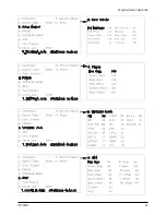
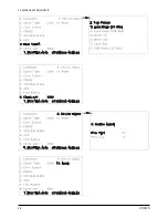
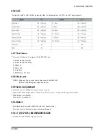
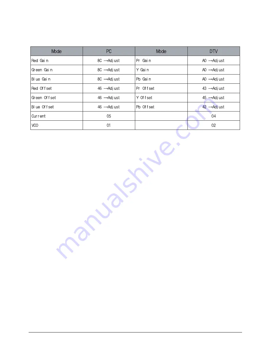
4-3-6 ADC
*Adjust the R(Pr), G(Y), B(Pb) gain and offset to the basic level of DTV and PC input signals.
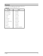
4-3-7 Test Pattern
* It is only displayed to a signal of the PW565 data.
1) Luma Ramp (16 step)
2) Luma Ramp (128 Step)
3) White 16
4) White 240
5) Color Bar
6) RGB Ramp (32 Step)
4-3-8 Check sum
* XXXX : Displays the current check sum size of the MICOM.
(Varies depending on program update)
4-3-9 Service Adjustement
* Used where it is difficult to receive stereo sound.
* Adjust the ‘Pilot High’ and/or ‘Pilot Low’ data to vary voltage receiving stereo sound.
* Pilot High : 16 (default)
Pilot Low : 10 (default)
4-3-10 Reset
* Initializes the data in the MICOM. (Set to default value)
The values set in factory mode remain unchanged.
4-3-11 T_VIC17NUS_1018 07/05/2003 18:12:26
* Displays the MICOM program version
Summary of Contents for LT17N23W
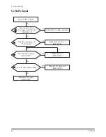
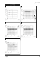
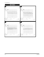
Page 4: ...5 Troubleshooting 5 2 LT17N23W WAVEFORMS 1 1 1 2 1 3 1 4...
Page 5: ...WAVEFORMS 1 5 1 6 1 7 5 Troubleshooting LT17N23W 5 3...
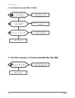
Page 7: ...5 Troubleshooting LT17N23W 5 5 WAVEFORMS 2 1 2 2 2 3 2 5 2 4...
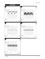
Page 9: ...5 Troubleshooting LT17N23W 5 7 WAVEFORMS 3 1 3 2 3 3 3 4 3 5...
Page 10: ...5 Troubleshooting 5 8 LT17N23W WAVEFORMS 3 6 3 7 3 8 3 9...
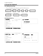
Page 14: ...4 Alignments and Adjustments LT17N23W 4 3...
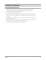
Page 15: ...4 Alignments and Adjustments 4 4 LT17N23W...
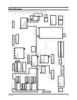
Page 21: ...8 Block Diagram This Document can not be used without Samsung s authorization LT17N23W 8 1...

