


TFT-LCD TV
Chassis
Model
GPL15KE
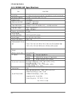
LW15M23CP
GPL17KE
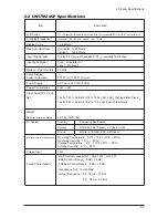
LW17M24CP
GPL20KE
LW20M21CP
Manual
SERVICE
TFT-LCD TV
Fashion Feature
- Easy-to-use remote control
- Easy-to-use on-screen menu system
- Automatic timer to turn the TV on and off
- Automatic channel tuning for up to 194
channels. (Air : 69 , STD : 125 )
- A special filter to reduce or eliminate
reception problems
- Fine tuning control for the sharpest picture
possible
- Built-in, dual channel speakers
- Headphone jack for private listening
Summary of Contents for LW15M23CP
Page 6: ...Memo 1 Precautions 1 4 ...
Page 23: ...4 Troubleshooting 4 3 WAVEFORMS 1 2 5 3 6 4 4 7 8 ...
Page 26: ...4 Troubleshooting 4 6 Memo ...
Page 29: ...5 Exploded View Parts List 5 3 5 2 LW17M24CP T0003 M0215 T0447 M0147 M0003 M0014 M0013 ...
Page 31: ...5 Exploded View Parts List 5 5 5 3 LW20M21CP T0003 M0215 M0147 M0014 M0013 M0014 ...
Page 63: ...7 Block Diagrams 7 1 7 Block Diagram ...
Page 64: ...Memo 7 Block Diagrams 7 2 ...
Page 66: ...8 Wiring Diagrams 8 2 Memo ...
Page 68: ...9 Schematic Diagrams 9 2 1 2 5 3 6 4 7 8 ...
Page 70: ...9 Schematic Diagrams 9 4 9 ...
Page 73: ...9 Schematic Diagrams 9 7 ...
Page 74: ...9 Schematic Diagrams 9 8 ...
Page 76: ...9 Schematic Diagrams 9 10 ...
Page 78: ...9 Schematic Diagrams 9 2 1 2 5 3 6 4 7 8 ...
Page 80: ...9 Schematic Diagrams 9 4 9 ...
Page 83: ...9 Schematic Diagrams 9 7 ...
Page 84: ...9 Schematic Diagrams 9 8 ...
Page 86: ...9 Schematic Diagrams 9 10 ...
Page 88: ...9 Schematic Diagrams 9 2 1 2 5 3 6 4 7 8 ...
Page 90: ...9 Schematic Diagrams 9 4 9 ...
Page 93: ...9 Schematic Diagrams 9 7 ...
Page 94: ...9 Schematic Diagrams 9 8 ...
Page 96: ...9 Schematic Diagrams 9 10 ...
Page 126: ...12 PCB Layout 12 2 12 1 2 Power board LW15M23CP ...
Page 127: ...12 PCB Layout 12 3 12 1 2 Power board LW17M24CP LW20M21CP ...
Page 128: ...12 PCB Layout 12 4 Memo ...
Page 129: ...13 Circuit Descriptions 13 1 13 Circuit Descriptions 13 1 Overall Block Structure ...
Page 130: ...13 Circuit Descriptions 13 2 13 2 1 MAIN BOARD POWER TREE 13 2 Partial Block Description ...
Page 132: ...13 Circuit Descriptions 13 4 ...
Page 133: ...13 Circuit Descriptions 13 1 13 Circuit Descriptions 13 1 Overall Block Structure ...
Page 134: ...13 Circuit Descriptions 13 2 13 2 1 MAIN BOARD POWER TREE 13 2 Partial Block Description ...
Page 136: ...13 Circuit Descriptions 13 4 ...


