


10 Operating Installations and Installation
10-9
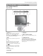
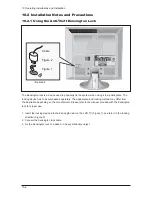
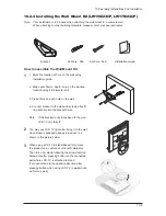
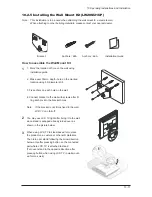
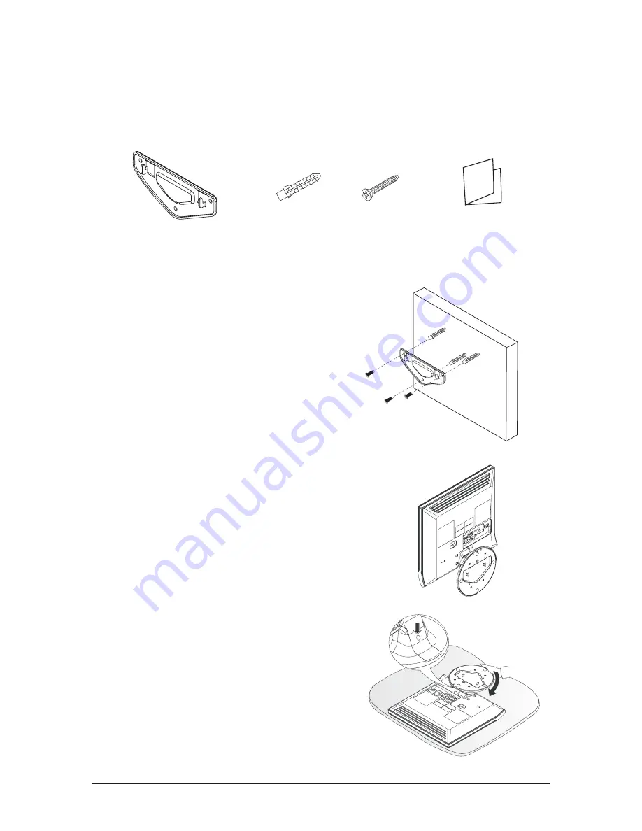
10-2-4 Installing the Wall Mount Kit(LW15M23CP, LW17M24CP)
Note : This installation is to be used when attaching the wall mount to a concrete wall.
When attaching to other building materials, please contact your nearest dealer.
Bracket
Anchors : 3EA
Anchors : 3EA
Installation Guide
1. Mark the location of hole on the wall using
installation guide.
2. Make over 35mm- depth- hole on the marked
location using 5.0-diameter drill.
3. Fix anchors on each hole on the wall.
4. Connect bracket to the wall with screws after fit
ting anchors into the bracket holes.
Note : If the bracket is not firmly fixed to the wall,
LCD TV can fall off.
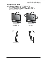
You may use LCD TV right after fixing it to the wall
since stand is wrapped already turned over as
shown in the picture below.
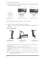
When using LCD TV in stand-based form, place
the product on a cushion or other soft materials.
Then turn over stand following the arrow direction
below only after pressing button on the connected
part where LCD TV is attached to stand.
(Turn over stand in the opposite direction after
pressing button when using LCD TV in wall-mount-
ed form as well.)
1
2
3
How to assemble the Wall Mount Kit
Summary of Contents for LW15M23CP
Page 6: ...Memo 1 Precautions 1 4 ...
Page 23: ...4 Troubleshooting 4 3 WAVEFORMS 1 2 5 3 6 4 4 7 8 ...
Page 26: ...4 Troubleshooting 4 6 Memo ...
Page 29: ...5 Exploded View Parts List 5 3 5 2 LW17M24CP T0003 M0215 T0447 M0147 M0003 M0014 M0013 ...
Page 31: ...5 Exploded View Parts List 5 5 5 3 LW20M21CP T0003 M0215 M0147 M0014 M0013 M0014 ...
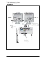
Page 63: ...7 Block Diagrams 7 1 7 Block Diagram ...
Page 64: ...Memo 7 Block Diagrams 7 2 ...
Page 66: ...8 Wiring Diagrams 8 2 Memo ...
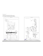
Page 68: ...9 Schematic Diagrams 9 2 1 2 5 3 6 4 7 8 ...
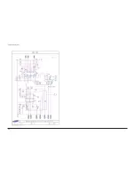
Page 70: ...9 Schematic Diagrams 9 4 9 ...
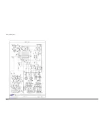
Page 73: ...9 Schematic Diagrams 9 7 ...
Page 74: ...9 Schematic Diagrams 9 8 ...
Page 76: ...9 Schematic Diagrams 9 10 ...
Page 78: ...9 Schematic Diagrams 9 2 1 2 5 3 6 4 7 8 ...
Page 80: ...9 Schematic Diagrams 9 4 9 ...
Page 83: ...9 Schematic Diagrams 9 7 ...
Page 84: ...9 Schematic Diagrams 9 8 ...
Page 86: ...9 Schematic Diagrams 9 10 ...
Page 88: ...9 Schematic Diagrams 9 2 1 2 5 3 6 4 7 8 ...
Page 90: ...9 Schematic Diagrams 9 4 9 ...
Page 93: ...9 Schematic Diagrams 9 7 ...
Page 94: ...9 Schematic Diagrams 9 8 ...
Page 96: ...9 Schematic Diagrams 9 10 ...
Page 126: ...12 PCB Layout 12 2 12 1 2 Power board LW15M23CP ...
Page 127: ...12 PCB Layout 12 3 12 1 2 Power board LW17M24CP LW20M21CP ...
Page 128: ...12 PCB Layout 12 4 Memo ...
Page 129: ...13 Circuit Descriptions 13 1 13 Circuit Descriptions 13 1 Overall Block Structure ...
Page 130: ...13 Circuit Descriptions 13 2 13 2 1 MAIN BOARD POWER TREE 13 2 Partial Block Description ...
Page 132: ...13 Circuit Descriptions 13 4 ...
Page 133: ...13 Circuit Descriptions 13 1 13 Circuit Descriptions 13 1 Overall Block Structure ...
Page 134: ...13 Circuit Descriptions 13 2 13 2 1 MAIN BOARD POWER TREE 13 2 Partial Block Description ...
Page 136: ...13 Circuit Descriptions 13 4 ...


