4 Alignments and Adjustments
LW17M24C/LW20M21C
4-5
7. Test Pattern ( Test Pattern of VCTi)
1) VCTi
2) Toshiba
3) Gray Bar
4) Gray
5) Green
6) Color Bar
7) Cross
8. Bus Stop
- Bus stop is used data communication.
9. Chcek Sum
- Display the current check sum size of the MICOM.
10. Reset
- Initializes the data in the MICOM.
11. T-VNC17(20) PEU-0003 2004/04/20
- Display the MICOM program version.
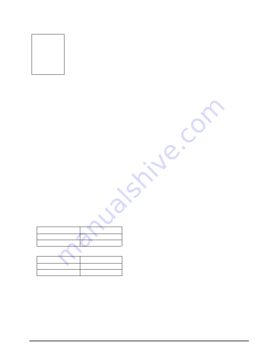
4-2-3 White Balance
High
Low
285, 295
285, 295
x, y
x, y
High
Low
285, 295
280, 295
x, y
x, y
LW17M24C
LW20M21C
Summary of Contents for LW17M24C
Page 7: ...Memo 2 Product Specifications 2 4 LW17M24C LW20M21C ...
Page 11: ...Memo 3 Disassembly and Reassembly 3 4 LW17M24C LW20M21C ...
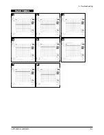
Page 19: ...5 Troubleshooting LW17M24C LW20M21C 5 3 WAVEFORMS 1 2 5 3 6 4 4 7 8 ...
Page 22: ...Memo 5 Troubleshooting 5 6 LW17M24C LW20M21C ...
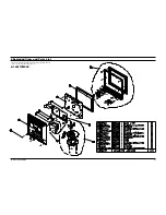
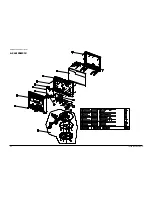
Page 24: ...6 Exploded View Parts List 6 2 LW17M24C LW20M21C 6 2 LW20M21C ...
Page 50: ...9 Schematic Diagrams 9 2 LW17M24C LW20M21C Memo ...
Page 52: ...10 PCB Layout 10 2 LW17M24C LW20M21C Memo ...
Page 54: ...11 Schematic Diagrams 11 2 LW17M24C LW20M21C 1 2 5 3 6 4 7 8 ...
Page 56: ...11 Schematic Diagrams 11 4 LW17M24C LW20M21C 9 ...
Page 62: ...11 Schematic Diagrams 11 10 LW17M24C LW20M21C Memo ...
Page 64: ...www s manuals com ...


