background image

SERVICE

MICROWAVE OVEN

CONTENTS

MICROWAVE OVEN

1. Precaution

2. Specifications

3. Operating Instructions

4. Disassembly and Reassembly

5. Alignment and Adjustments

6. Troubleshooting

7. Exploded Views and Parts List

8. Schematic Diagrams

Manual

M1711NR

BWT

Summary of Contents for M1711NR

Page 1: ...CONTENTS MICROWAVE OVEN 1 Precaution 2 Specifications 3 Operating Instructions 4 Disassembly and Reassembly 5 Alignment and Adjustments 6 Troubleshooting 7 Exploded Views and Parts List 8 Schematic Diagrams Manual M1711NR BWT ...

Page 2: ...s and latches 5 evidence of dropping or abuse c Before turning on microwave power for any service test or inspection within the microwave generating compartments check the magnetron wave guide or transmission line and cavity for proper alignment integrity and connections d Any defective or misadjusted components in the interlock monitor door seal and microwave generation and transmission systems s...

Page 3: ...hould remove their watches while repairing an MWO 11 To avoid any possible radiation hazard replace parts in accordance with the wiring diagram Also use only the exact replacements for the following parts Primary and secondary interlock switches interlock monitor switch 12 If the fuse is blown by the Interlock Monitor Switch Replace all of the following at the same time Primary door sensing switch...

Page 4: ...igure 1 1 2 The high voltage capacitor remains charged about 30 seconds after disconnection Short the negative terminal of the high voltage capacitor to to the oven chassis Use a screwdriver 3 High voltage is maintained within specified limits by close tolerance safety related components and adjustments If the high voltage exceeds the specified limits check each of the special components PRECAUTIO...

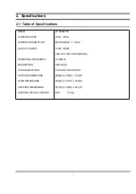
Page 5: ...RATING FREQUENCY MAGNETRON COOLING METHOD OUTSIDE DIMENSIONS OVEN DIMENSIONS SHIPPING DIMENSIONS SHIPPING WEIGHT APPROX 35 MINUTES 230V 50Hz MICROWAVE 1 150W 100W 800W IEC 705 TEST PROCEDURE 2 450MHz OM75S 31 COOLING FAN MOTOR 489 W x 275 H x 374 D 306 W x 211 H x 320 D 557 W x 329 H x 451 D NET 13 5kg ...

Page 6: ...ontrol Panel 3 2 Features External Views VENTILATION HOLES LIGHT VARIABLE COOKING POWER CONTROL KNOB TIMER KNOB COUPLER DOOR DOOR LATCHES OPEN DOOR PUSH BUTTON SAFETY INTERLOCK HOLES ROLLER RING TURNTABLE 275mm 206mm 374mm 489mm 342mm ...

Page 7: ... does not hit any adjacent parts or it may be damaged NOTE2 When replacing the magnetron be sure to remount the magnetron gasket in the correct position and make sure the gasket is in good condition 4 2 Replacement of High Voltage Transformer 1 Discharge the high voltage capacitor 2 Disconnect all the leads 3 Remove the mounting bolts 4 Reconnect the leads correctly and firmly PRECAUTION Serviceme...

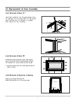
Page 8: ...ragile Then remove the door assembly 4 3 2 Removal of Door E Following the procedure as shown in the figure insert and bend a thin metal plate between Door E and Door A until you hear the tick sound 1 Insertion depth of the thin metal plate should be 0 5mm or less 4 3 3 Removal of Key Door Spring Remove pin hinge from Door E Detach spring from Door E and key door Door E Door A Door C 90 ...

Page 9: ...operate properly check if any other part such as the control circuit board blower motor or high voltage transformer is defective 4 5 Replacement of Drive Motor 1 Take out the glass tray guide roller and coupler from cavity 2 Turn the oven upside down to replace the drive motor 3 Remove a screw securing the drive motor cover 4 Disconnect all the lead wires from the drive motor 5 Remove screws secur...

Page 10: ...4 6 1 Removal of Control Box Assembly 1 Disconnect the connectors from the control box assembly 2 Remove screws securing the control box assembly 3 Remove the knobs of the control box A ssy 4 Remove the screw securing the timer CONTROL BOX SCREWS ...

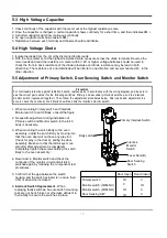
Page 11: ...it by disconnecting its leads 3 A continuity check across the magnetron filament terminals should indicate one ohm or less 4 A continuity check between each filament terminal and magnetron case should read open PRECAUTION 1 High voltage is present at the high voltage terminals during any cook cycle 2 It is neither necessary nor advisable to attempt measurement of the high voltage 3 Before touching...

Page 12: ...tch Body to the oven assembly adjust the Latch Body by moving it so that the oven door will not have any play in it Check for play in the door by pulling the door assembly Make sure that the latch keys move smoothly after adjustment is completed Completely tighten the screws holding the Latch Body to the oven assembly 4 Reconnect to Monitor switch and check the continuity of the monitor circuit an...

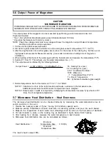
Page 13: ...edure will cause a variance in the temperature rise Additional power test should be made if temperature rise is marginal NOTE 2 Output power in watts is computed by multiplying the temperature rise step 5 by a factor of 91 times the of centigrade temperature 5 7 Microwave Heat Distribution Heat Evenness The microwave heat distribution can be checked indirectly by measuring the water temperature ri...

Page 14: ...n at the highest power level 4 Set survey meter dual ranges to 2 450MHz 5 Using the survey meter and spacer cone as described above measure near the opening of magnetron the surface of the air guide and the surface of the wave guide as shown in the following photo but avoid the high voltage components The reading should be less than 4mW cm2 5 10 Note on Measurement 1 Do not exceed the limited scal...

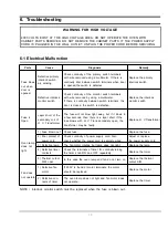
Page 15: ...ns secondary open the transformer may be faulty Replace H V Transformer Oven lamp does not light 1 Fuse blown out Check fuse Replace the fuse 2 Poor contact of power cord Check continuity of power supply cord Also check whether the power cord is securely wired Adjust or replace the power supply cord 3 Defective lamp The fan motor rotates but lamp does not light Replace the lamp 4 Defective timer c...

Page 16: ...well to the door hinge Fasten or tighten Timer does not operate 1 Defective timer motor If the timer does not operate with 21V applied to the terminals the timer motor amy be faulty Replace timer 2 Defective contacts of timer S W The lamp does not light Replace timer Cooking tray does not rotate 1 Defective drive motor Check to see if 21V exists at the motor terminals If so motor will be defective...

Page 17: ... and OFF repeatedly Replace or adjust 6 Open coil of H V Trans former Check the continuity of primary coil and secondary coil If there is no continuity H V Transformer is defective Replace the H V Transformer 7 Shorted H V capacitor Check the continuity of capacitor If the capacitor shorts the fuse blows Replace the H V Capacitor 8 Monitor fuse blown out Check the monitor fuse on the noise filter ...

Page 18: ...M001 M029 M049 M099 M039 M040 M042 M023 M017 M014 M019 M022 M020 M M 1 7 M035 M037 M015 W002 T001 T017 M034 M043 M036 M157 M038 M132 M048 B018 B006 B001 B009 B004 B002 M051 C007 C001 C006 C025 C005 C032 C024 C082 D049 D006 D005 D004 D003 D002 D011 D007 D015 ...

Page 19: ... MOTOR FAN SMF 3RDEA 230V50Hz 2400rpm 3rd 1 M029 DE47 20008A THERMOSTAT PW2N 52JC 100 60 250V 7 5A H 1 M034 DE67 00140A COUPLER NC2000 0 6 0 8 PPS ESS840 3G 1 M035 OM75S 31 ERHN ASSY MAGNETRON OM75S 31 ERHN 1 M036 4713 001046 LAMP INCANDESCENT 240V 104mA 25W ORG 1 M037 DE71 60457B COVER AIR 3RD 0 7 BTM PP 1 M038 DE26 00079A TRANS H V SHV EURO1 230V 50HZ 2130V 3 6V 1 M039 2501 001016 C OIL 950nF 2 ...

Page 20: ... RELAY POWER 240V 3750VA 15000MA 6MS 20 1 C082 DE94 00493L ASSY CONTROL BOX 230V50HZ M1711NR BWT PU 1 S N A D002 DE64 00277D DOOR A M1711NR BWT ABS PURE WHT 1 D003 DE63 00056B SCREEN DOOR M1711N G2711N SAN SMOG SILK 1 D004 DE92 50133C ASSY DOOR E MW4593G BLK 3RD 0 7 1 D005 DE01 00112A FILM DOOR PET L268 T0 15 W150 NTR 1 D006 DE64 40008B DOOR C PP CE745G BLK 1 D007 DE61 00198A SPRING KEY M1877 HSWR...

Page 21: ...2S SWRCH18A ZP2 PH PI5 L10 4 MGT DE60 10082H SCREW A 2S 4X12 TOOTHED 1 AIR COVER DE60 10082H SCREW A 2S 4X12 TOOTHED 2 B LATCH DE60 10082H SCREW A 2S 4X12 TOOTHED 3 B PLATE DE60 10082H SCREW A 2S 4X12 TOOTHED 1 C BLOWER DE60 10082H SCREW A 2S 4X12 TOOTHED 1 C BOX DE60 10082H SCREW A 2S 4X12 TOOTHED 4 O PANEL DE60 10098A SCREW ASSY TAP TITE GLD SWRCH18A ZPC2 PH TC M4X8 WT 1 D MOTOR DE60 30016A NUT ...

Page 22: ...grams This Document can not be used without Samsung s authorization MAGNETRON FA F RED RED RED RED SYMBOL COLOR BRN BROWN BLK BLACK RED RED BLU BLUE BLU BLU HIGH VOLTAGE TRANSFORMER HIGH VOLTAGE CAPACITOR HIGH VOLTAGE DIODE TO CHASSIS H V FUSE ...

Page 23: ...ectronics Co Ltd May 2003 Printed in Korea Code No DE68 03171A This Service Manual is a property of Samsung Electronics Co Ltd Any unauthorized use of Manual can be punished under applicable International and or domestic law ...

Page 24: ...d M002 W002 C005 D005 M001 B018 T001 D006 D004 D003 D002 D049 D011 D007 D015 C032 C025 C007 C006 C082 C001 C024 M029 M051 M099 M049 M048 M132 M039 M040 M038 M042 M043 M034 M037 M035 M036 M157 M023 M022 M020 M017 M014 M019 M015 B006 B001 B002 B009 T017 B004 ...

Reviews: